00197490-03_SM_CP20-P-M2_EN保养维护.pdf - 第45页
5 DP drives 5.3 Replacing the clamping plate at the DP drive Service Manual SIPLACE SpeedStar (C&P20 P / C&P20 M2) 03/2018 45 5.3 Replacing the clamping plate at the DP drive Parts ● Clamping plate [03005144-xx] …
5 DP drives
5.2 Replacing the DP drive hose
44 Service Manual SIPLACE SpeedStar (C&P20 P / C&P20 M2) 03/2018
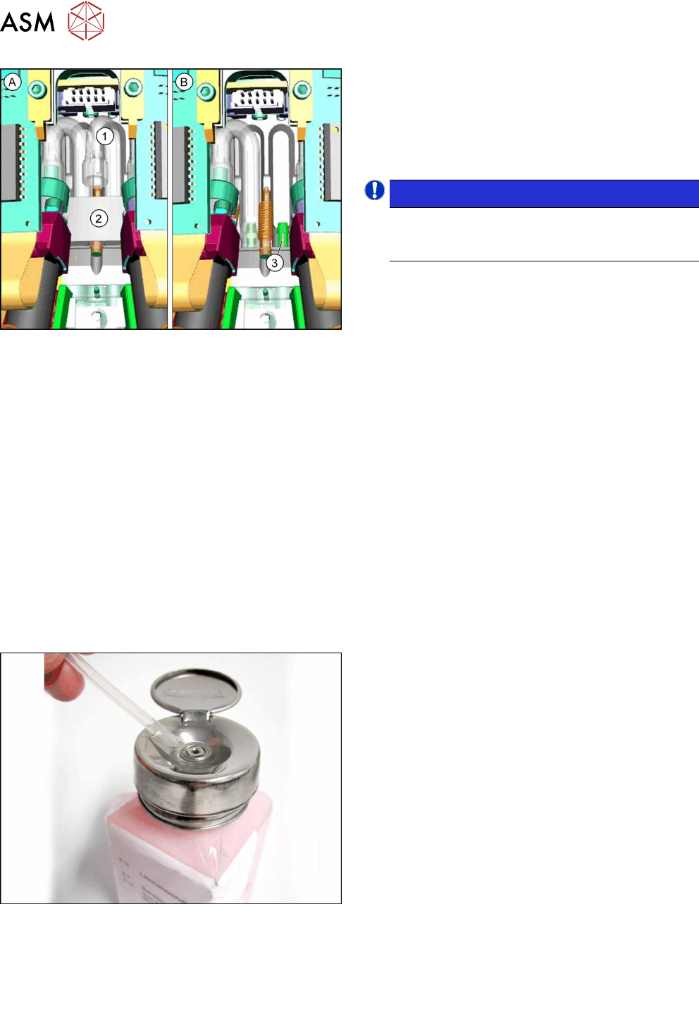
Fig.55: Hose and spring unit
A) Diagram with spring unit
B) Diagram with hidden spring unit
1. Hose
2. Spring unit
3. Back connection for hose
NOTICE!
The spring unit (2) can not be dismantled. This
has just been hidden in diagram B to give a
clearer view of the back connection.
.
Preparation
► Remove the head from the machine. For details about removing and fitting the placement
head, refer to the service manual for your machine.
Fit the head on the head mount [03056231‑xx].
► Make sure that the component sensor protective cap is fitted.
1.1.3 "Safety instructions for the component sensor" [}6]
Removal
► Dismantle the holding circuit/aperture ring.
7.1 "Replacing the holding circuit/reflecting ring" [}61]
► Dismantle the DP drive.
5.1 "Replacing the DP drive" [}39]
► Pull the back end of the hose off.
Installation
Fig.56: Coat the hose with ethanol
► Coat the new hose at one end with ethanol.
► Use the tweezers to push the coated end onto
the connection behind the spring unit.
Observe the natural bending radius of the hose.
Make sure that you only use the "tweezers blunt
145 mm size 3 mm" [00376493-xx].
► Follow the removal instructions in reverse order for further installation.
Also observe the installation instructions in the following sections:
5.1 "Replacing the DP drive" [}39]
7.1 "Replacing the holding circuit/reflecting ring" [}61]
► Observe in particular the torques specified!
5 DP drives
5.3 Replacing the clamping plate at the DP drive
Service Manual SIPLACE SpeedStar (C&P20 P / C&P20 M2) 03/2018 45
5.3 Replacing the clamping plate at the DP drive
Parts
●
Clamping plate [03005144-xx]
Overview
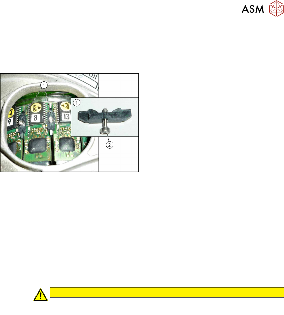
Fig.57: Clamping plate fastening screw
1. Clamping plates
2. Screw fastening the clamping plate
Torque: 0.1Nm
Preparation
► Remove the head from the machine. For details about removing and fitting the placement
head, refer to the service manual for your machine.
Fit the head on the head mount [03056231‑xx].
► Make sure that the component sensor protective cap is fitted.
1.1.3 "Safety instructions for the component sensor" [}6]
Removal
► Remove the screw fastening the clamping plate and then take the clamping plate off.
Installation
► Follow the removal instructions in reverse order for further installation. Also observe the fol-
lowing instructions:
CAUTION
Installation instructions
► Tighten the screw fastening the clamping plate with a torque of 0.1 Nm.

5 DP drives
5.3 Replacing the clamping plate at the DP drive
46 Service Manual SIPLACE SpeedStar (C&P20 P / C&P20 M2) 03/2018