00197490-03_SM_CP20-P-M2_EN保养维护.pdf - 第48页
6 Pressure control valve (PRV) 6.1 Replacing the PRV 48 Service Manual SIPLACE SpeedStar (C&P20 P / C&P20 M2) 03/2018 Removal Fig.60: Disconnecting the energy and data supply cable ► Remove the two screws fasten…
6 Pressure control valve (PRV)
6.1 Replacing the PRV
Service Manual SIPLACE SpeedStar (C&P20 P / C&P20 M2) 03/2018 47
6 Pressure control valve (PRV)
6.1 Replacing the PRV
Parts
●
Pressure control valve (PRV) [03106620‑xx]
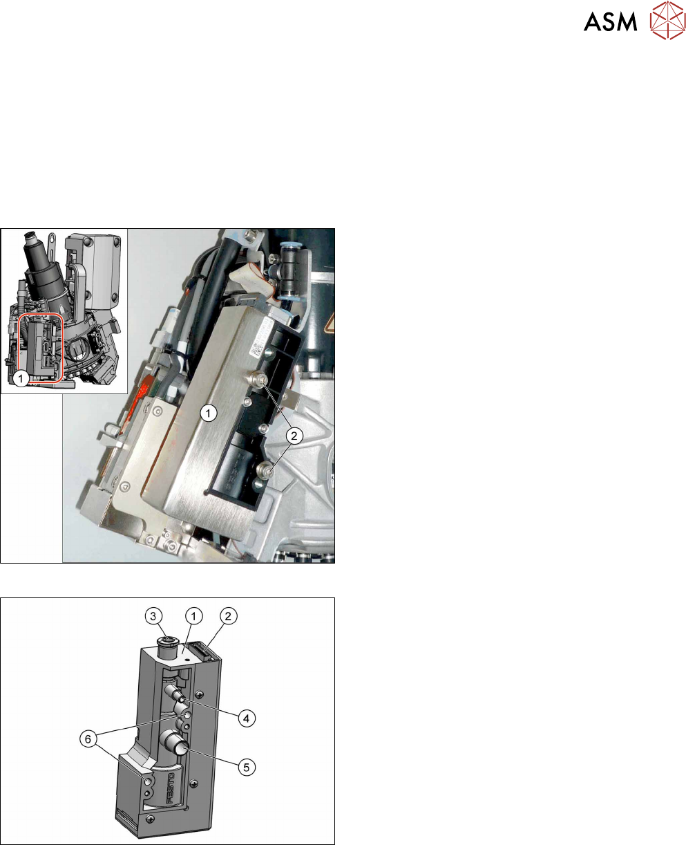
Overview
Fig.58: Pressure control valve fastening screws
1. Pressure control valve (PRV)
2. Two fastening screws
Torque: 0.9Nm
Fig.59: Overview of PRV
1. Strain relief with intermediate plate
2. Energy and data supply
3. Compressed air connection
4. Vacuum/air blast for pickup/placement circuit
5. Exhaust air, for cooling the X linear motor
6. Fastening screws on PRV
The pressure control valve supplies the pickup/place-
ment circuit with vacuum during the pickup process
and switches over to air blast during placement.
Preparation
► Remove the head from the machine. For details about removing and fitting the placement
head, refer to the service manual for your machine.
Fit the head on the head mount [03056231‑xx].
► Make sure that the component sensor protective cap is fitted.
1.1.3 "Safety instructions for the component sensor" [}6]
6 Pressure control valve (PRV)
6.1 Replacing the PRV
48 Service Manual SIPLACE SpeedStar (C&P20 P / C&P20 M2) 03/2018
Removal
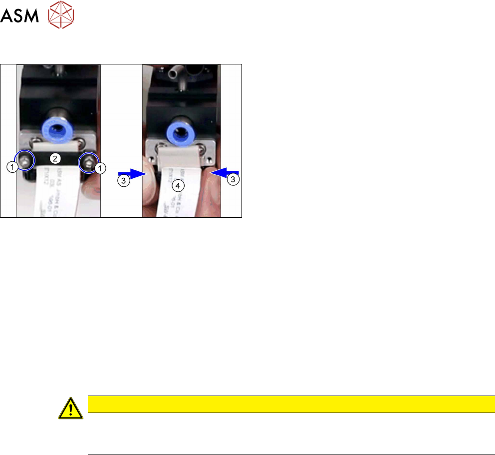
Fig.60: Disconnecting the energy and data supply cable
► Remove the two screws fastening the strain re-
lief(1) and then remove the strain relief (2).
► Press the two locks(3) together and unplug the
energy and data supply cable(4).
► Open the cable clamp fastening the cable to the component camera.
► Disconnect the hoses to the compressed air and from the vacuum/blast air and exhaust air. If
necessary, mark their positions to make clear assignment easier later on.
► Remove the two screws fastening the PRV and then remove the PRV.
Installation
► Fit the new PRV. Tighten the screws fastening the PRV with a torque of 0.9Nm.
► Reconnect to the electrical and compressed air systems.
Pay attention to the locking of the connectors.
► Follow the removal instructions in reverse order for further installation. Also observe the fol-
lowing instructions:
CAUTION
Installation instructions
► Perform "zero correction" for the pressure control valve. (See section 6.4 "Calibrating
the digital PRV" [}60]).
6 Pressure control valve (PRV)
6.2 Replacing the membrane and other small parts on the PRV
Service Manual SIPLACE SpeedStar (C&P20 P / C&P20 M2) 03/2018 49
6.2 Replacing the membrane and other small parts on the
PRV
NOTICE
Example shown as diagram
Depending on the version of your pressure control valve (DRV), there may be minor devi-
ations from this (e.g. material, color). However, the procedure is the same for all PRV.
Parts
Select the required spare part:
●
Self-tapping screws:
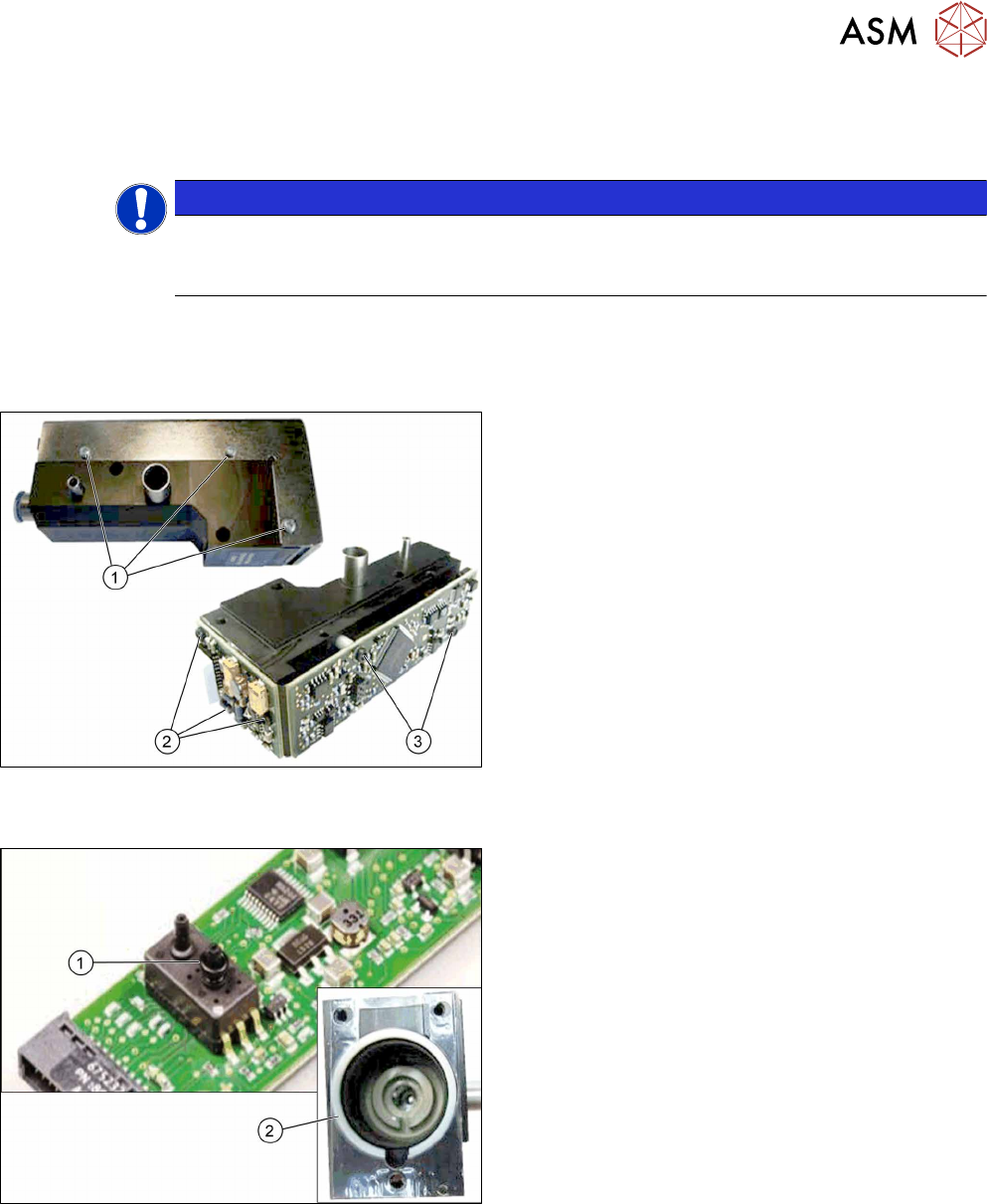
Fig.61: Screws
1. Self-tapping screw PT-WN1442-2.5X6-PT10
[03119666‑xx]
Self-tapping screw PT-WN1413-2.5X6-PT10
[03119678‑xx]
2. Self-tapping screw PT-WN1442-2.5X8-PT10
[03119677‑xx]
3. Self-tapping screw PT-WN1412-2.5X14-PT10
[03119676‑xx]
●
O-ring / centering ring:
Fig.62: O-ring / centering ring:
1. O-ring I3601 B-1.5X1.08-N-NBR70
[03119672‑xx]
2. Centering ring VADI-MPPE-QS6-24VDC–SA
[03119675‑xx]