00197490-03_SM_CP20-P-M2_EN保养维护.pdf - 第59页
6 Pressure control valve (PRV) 6.3 Replacing the exhaust tube Service Manual SIPLACE SpeedStar (C&P20 P / C&P20 M2) 03/2018 59 6.3 Replacing the exhaust tube Parts ● Silicone hose (Di 8, Da 12, conductive, 1m) […
6 Pressure control valve (PRV)
6.2 Replacing the membrane and other small parts on the PRV
58 Service Manual SIPLACE SpeedStar (C&P20 P / C&P20 M2) 03/2018
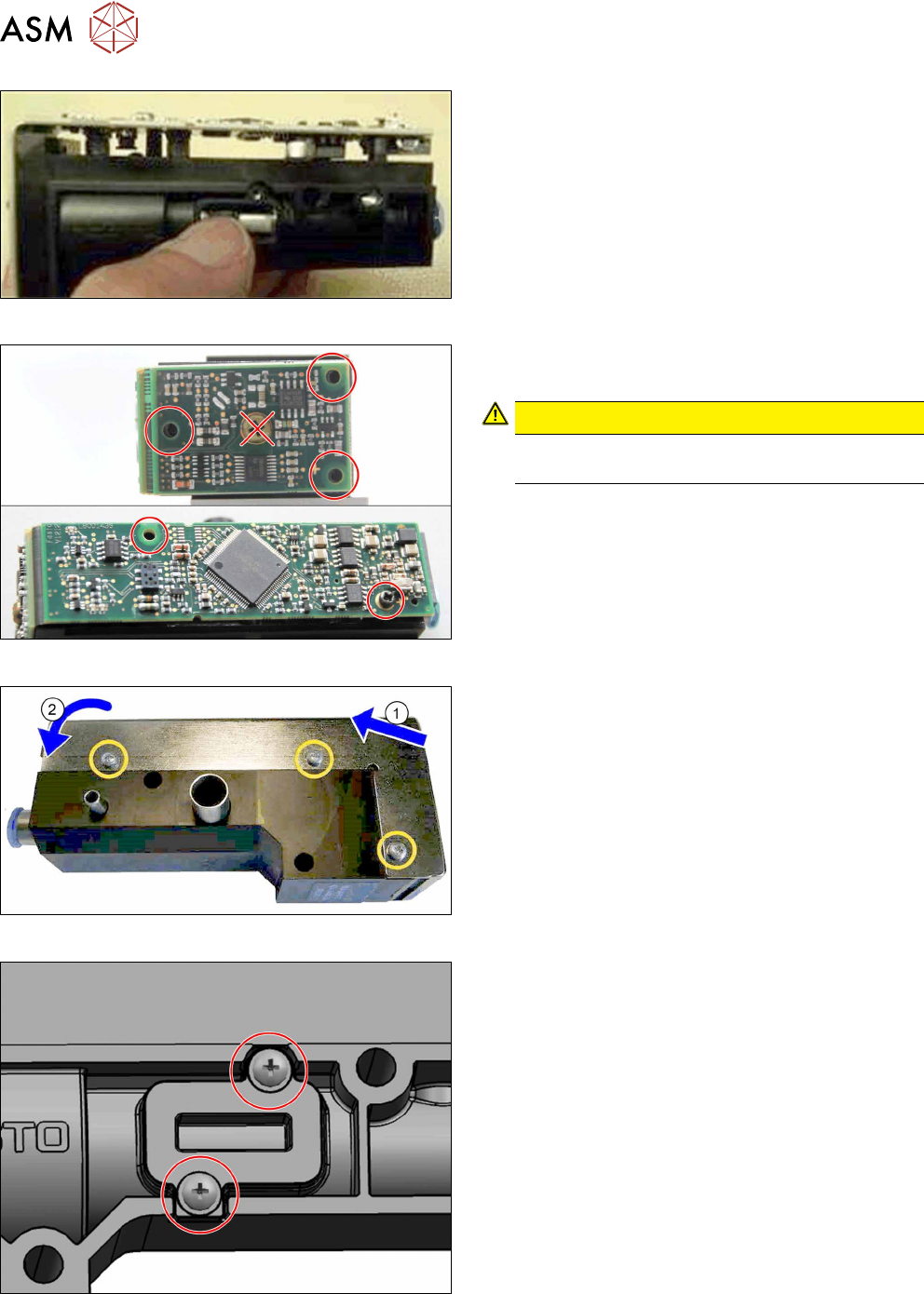
Fig.88: Positioning the top part of the board
► Place the top part of the board onto the housing.
Fig.89: Fastening the board
Fasten the board with five self-tapping screws. To do
so, proceed as follows:
CAUTION!
If possible, always use new screws of type PT-
WN1442-2.5X8-PT10.
.
► First check the thread by turning the screws
slightly to the left.
► Then fasten the screws with a torque of 0.2Nm.
Fig.90: Fitting the cover
► (1) Fit the cover at the top and (2) close it over
the printed circuit board.
► Fasten the cover with three screws. To do so,
proceed as follows:
– First check the thread by turning the screws
slightly to the left.
– Then fasten the screws with a torque of
0.2Nm.
Fig.91: Fitting the cover
► Fix the membrane cover into place on the PRV
with two screws.
► Follow the removal instructions in reverse order for further installation.
Also observe the installation instructions in the following section:
6.1 "Replacing the PRV" [}47]
6 Pressure control valve (PRV)
6.3 Replacing the exhaust tube
Service Manual SIPLACE SpeedStar (C&P20 P / C&P20 M2) 03/2018 59
6.3 Replacing the exhaust tube
Parts
●
Silicone hose (Di 8, Da 12, conductive, 1m) [03006727Sxx] (replaces: [03095873‑xx])
Overview
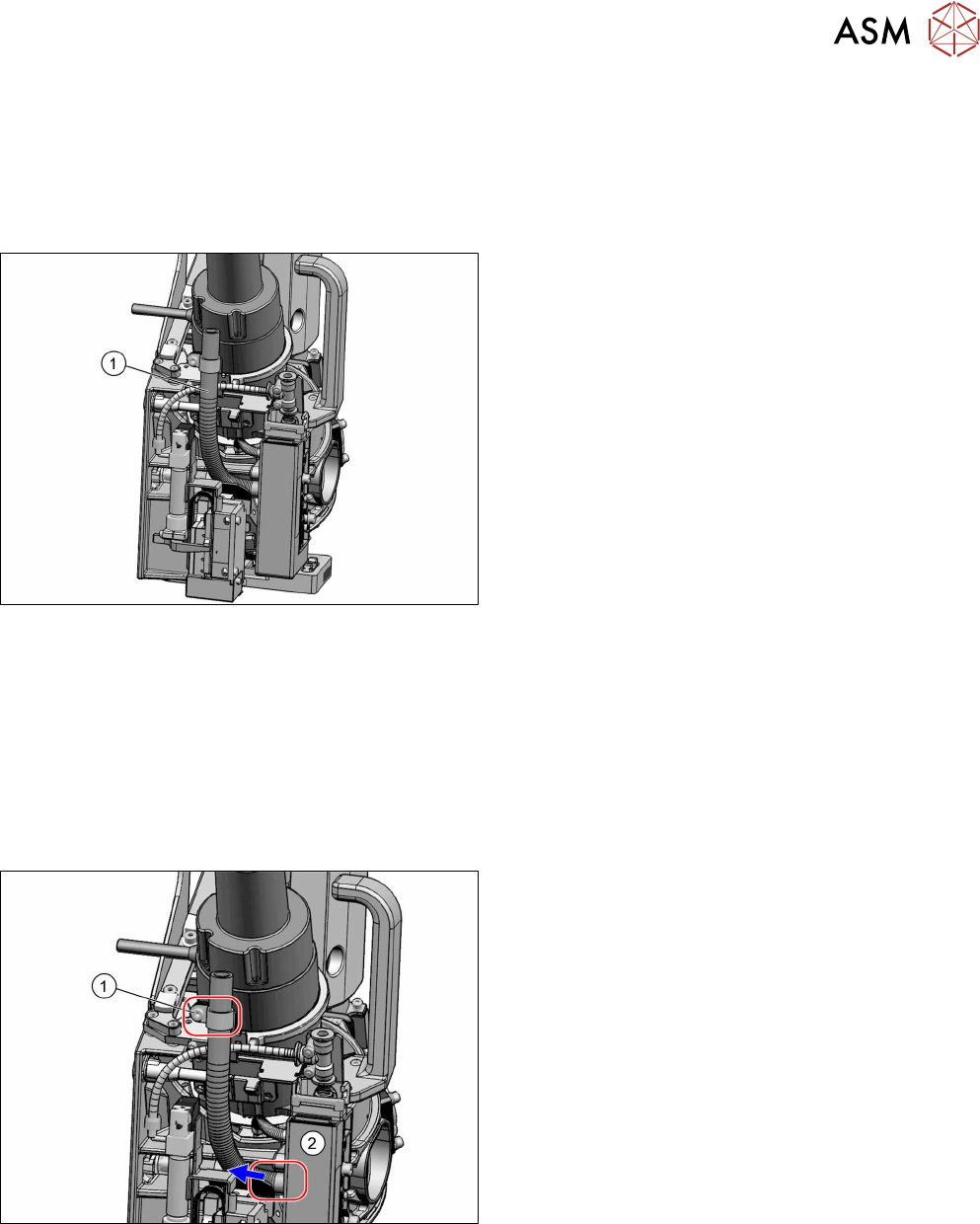
Fig.92: Exhaust air hose on the SIPLACE C&P20P
●
Exhaust air hose on the SIPLACE C&P20P
Length: 355mm
Preparation
► Remove the head from the machine. For details about removing and fitting the placement
head, refer to the service manual for your machine.
Fit the head on the head mount [03056231‑xx].
► Make sure that the component sensor protective cap is fitted.
1.1.3 "Safety instructions for the component sensor" [}6]
Removal
Fig.93: Exhaust air hose
► Open the hose clamp(1).
► Unplug the exhaust air hose from the pressure
control valve (2).
Installation
► Cut the new hose to a length of 355mm.
► Follow the removal instructions in reverse order for further installation.
6 Pressure control valve (PRV)
6.4 Calibrating the digital PRV
60 Service Manual SIPLACE SpeedStar (C&P20 P / C&P20 M2) 03/2018
6.4 Calibrating the digital PRV
The digital PRV is part of the placement head and generates the vacuum and the blast air for the
pickup and placement process. The zero point calibration of the digital PRV must be performed on
initial startup by the customer and then checked again after replacement of the digital PRV or the
placement head and recalibrated if necessary.
The zero point calibration is used to set the motor in the digital PRV into a neutral or central posi-
tion so that there is no vacuum or air blast at the nozzle.
6.4.1 Zero point calibration of pressure control valve
NOTICE
From SW706 this function is performed automatically (automatic calibration menu).
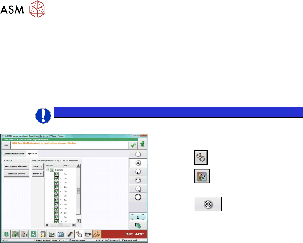
Fig.94: Set pressure to zero (SW710, example of SIPLACE
CPP)
► Switch over to operator level SIPLACE (cus-
tomer).
► Click the
button.
► Click the
button.
► Select the placement head.
► Click the
button.
► Go to the Specialized tab.
► Click on the Zero pressure adjustment button.