00197490-03_SM_CP20-P-M2_EN保养维护.pdf - 第65页
7 Holding circuit, aperture ring and silencer 7.1 Replacing the holding circuit/reflecting ring Service Manual SIPLACE SpeedStar (C&P20 P / C&P20 M2) 03/2018 65 Removal Fig.98: Dismantling the cover ► Remove the…
7 Holding circuit, aperture ring and silencer
7.1 Replacing the holding circuit/reflecting ring
64 Service Manual SIPLACE SpeedStar (C&P20 P / C&P20 M2) 03/2018
Torques in vacuum pump operation
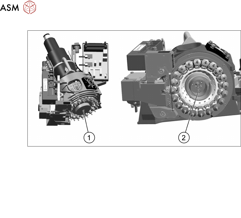
Fig.97: Cover and aperture ring
1 Cover
Fastening screw M3x14 (Allen key2.5)
Torque: hand-tight
2 Aperture ring
Three fastening screws M3x10
Torque: 1.3Nm
Torques in venturi operation
Silencer
Special screw M3 (SW10)
Torque: hand-tight
Holding circuit
Three fastening screws M3x10 (Allen
key2.5)
Torque: 0.25Nm
Preparation
► Remove the head from the machine. For details about removing and fitting the placement
head, refer to the service manual for your machine.
Fit the head on the head mount [03056231‑xx].
► Make sure that the component sensor protective cap is fitted.
1.1.3 "Safety instructions for the component sensor" [}6]
7 Holding circuit, aperture ring and silencer
7.1 Replacing the holding circuit/reflecting ring
Service Manual SIPLACE SpeedStar (C&P20 P / C&P20 M2) 03/2018 65
Removal
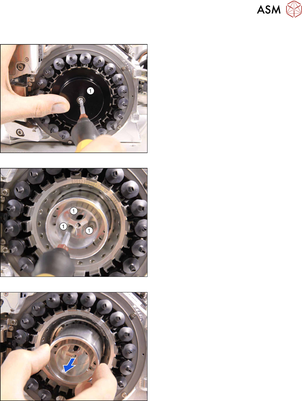
Fig.98: Dismantling the cover
► Remove the screw fastening the cover(1) and
then take the cover off.
Fig.99: Screws fastening the aperture ring
► Remove the three screws(1) fastening the aper-
ture ring.
Fig.100: Removing the aperture ring
► Carefully lever the aperture ring off the locating
pins. Make sure that the O-ring is not damaged.
7 Holding circuit, aperture ring and silencer
7.1 Replacing the holding circuit/reflecting ring
66 Service Manual SIPLACE SpeedStar (C&P20 P / C&P20 M2) 03/2018
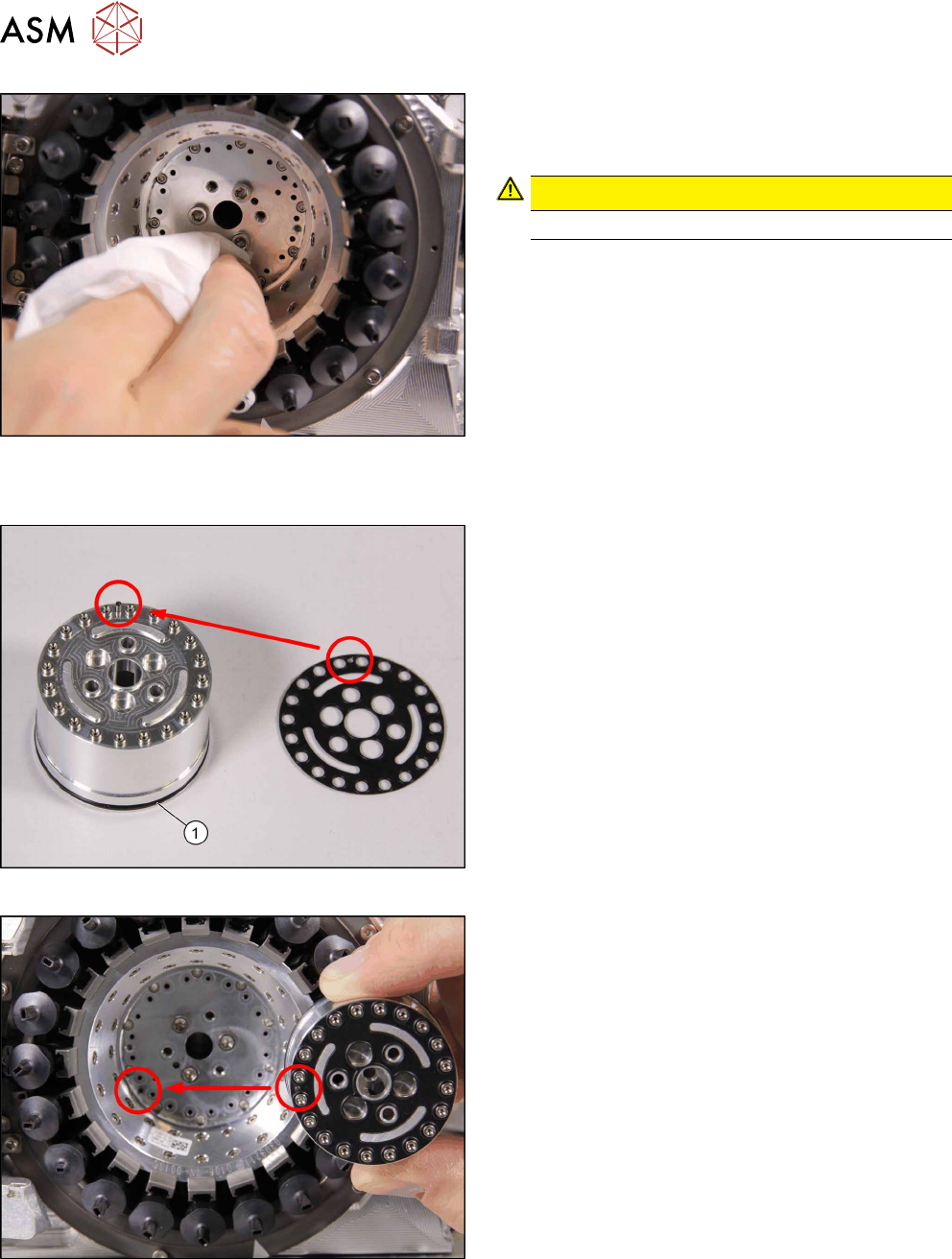
Fig.101: Cleaning
► Clean the seat of the aperture ring with a lint-free
cleaning cloth, if required.
CAUTION!
Do not use compressed air for cleaning!
.
Installation
Fig.102: O‑Ring and sealing disc
► If the O-ring (1) is damaged, replace it with a new
one.
► Correctly position the sealing disc on the aperture
ring. Make sure all openings are aligned.
Fig.103: Inserting the aperture ring
► Position the aperture ring (with sealing disc) cor-
rectly onto the locating pins in the star carrier.