00197490-03_SM_CP20-P-M2_EN保养维护.pdf - 第70页
7 Holding circuit, aperture ring and silencer 7.4 Vacuum sensor holding circuit board for SIPLACE C&P20P 70 Service Manual SIPLACE SpeedStar (C&P20 P / C&P20 M2) 03/2018
7 Holding circuit, aperture ring and silencer
7.4 Vacuum sensor holding circuit board for SIPLACE C&P20P
Service Manual SIPLACE SpeedStar (C&P20 P / C&P20 M2) 03/2018 69
Installation
► Follow the removal instructions in reverse order for further installation. Also observe the fol-
lowing instructions:
CAUTION
Installation instructions
► Carefully press the new silencer down, onto the holding circuit.
► Carefully hand-tighten the screw fastening the silencer.
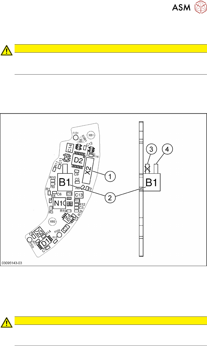
7.4 Vacuum sensor holding circuit board for SIPLACE
C&P20P
The "Vacuum sensor holding circuit SIPLACE C&P20P" board [03095143‑xx] is fitted on SIPLACE
C&P20P and C&P20M2 heads.
Fig.108: Vacuum sensor holding circuit board for SIPLACE C&P20P [03095143‑xx]
1 Plug X2 (to intermediate distributor) 2 Pressure sensor (holding circuit/aper-
ture ring)
3 Bottom hose connection on pressure
sensor
→ Do not use!
4 Top hose connection on pressure
sensor
CAUTION
Only use the top hose connection
The bottom hose connection(3) directly above the board must remain free.
► Only use the top hose connection(4).

7 Holding circuit, aperture ring and silencer
7.4 Vacuum sensor holding circuit board for SIPLACE C&P20P
70 Service Manual SIPLACE SpeedStar (C&P20 P / C&P20 M2) 03/2018
8 Return unit and return cylinder
8.1 Replacing the return unit
Service Manual SIPLACE SpeedStar (C&P20 P / C&P20 M2) 03/2018 71
8 Return unit and return cylinder
8.1 Replacing the return unit
Parts
●
Return unit [03007696-xx]
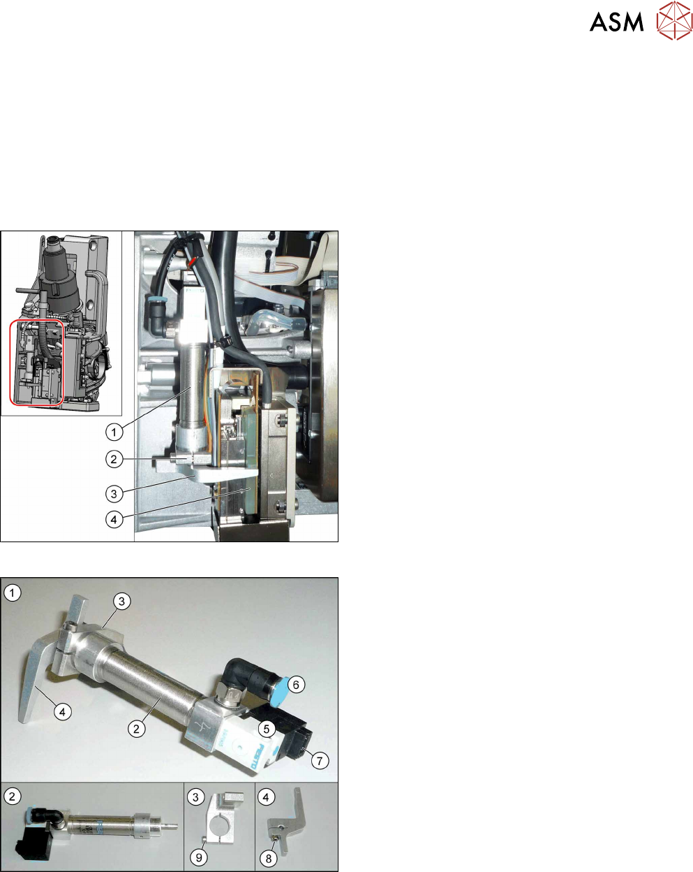
Overview
Fig.109: Overview of return unit on the head
1. Return cylinder
2. Return cylinder holder
3. Driver lever for Z axis
4. Rotor on Z motor
The return unit is installed on the Z axis and is re-
sponsible for protecting the Z axis from damage, by
moving it into a safe area in the case of unexpected
events (e.g. power cuts or machine shutdown).
Fig.110: Overview of return unit
1. Return unit assembly
2. Return cylinder
3. Return cylinder holder
4. Driver lever
5. Solenoid valve
6. Compressed air connection
7. Electrical connection
8. Fastening screw for driver lever (4)
9. Fastening screw for "return cylinder holder"(3)