00197490-03_SM_CP20-P-M2_EN保养维护.pdf - 第83页
11 Software functions 11.1 Zero point correction for the Star and Z axis Service Manual SIPLACE SpeedStar (C&P20 P / C&P20 M2) 03/2018 83 11 Software functions 11.1 Zero point correction for the Star and Z axis 1…

10 Miscellaneous
10.1 Replacing the handle
82 Service Manual SIPLACE SpeedStar (C&P20 P / C&P20 M2) 03/2018
11 Software functions
11.1 Zero point correction for the Star and Z axis
Service Manual SIPLACE SpeedStar (C&P20 P / C&P20 M2) 03/2018 83
11 Software functions
11.1 Zero point correction for the Star and Z axis
11.1.1 Transfer head specific data to the machine data after manual head exchange
NOTICE
Fast Head Exchange
If a head exchange is carried out with the FHE function, the head specific data will be auto-
matically transferred to the machine data.
Transferring head specific data manually
Precondition: The head needs to have been referenced (star and Z axis).
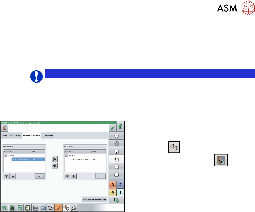
Fig.124: Zero correction data
► Switch over to operator level SIPLACE (cus-
tomer).
► Select Manual operations (Check sensors and
functions)
--> Check sensors and func-
tions of specific components
.
► Select the relevant head.
► Select Z axis.
► Select Zero correction data.
► In the Head EEPROM section, select the relevant
parameters, then click on Edit and enter the cor-
responding value.
► Use the arrow button of the head EEPROM to
transfer the data to the machine data.
► After correcting the parameters, select Write
head and machine data.
► Repeat these settings for the star axis.
11 Software functions
11.2 Calibration
84 Service Manual SIPLACE SpeedStar (C&P20 P / C&P20 M2) 03/2018
11.2 Calibration
Overview
With the calibration of the component camera the following values are determined:
the relationship of "camera pixel size to resolution of machine measuring system (X,Y)", the "cam-
era center point in X and Y direction" and the "torsion angle of the CCD sensor in the camera".
After that, the head offset and the segment offsets for the top and bottom are determined.
●
Head offset: the head offset is the distance between the PCB camera and the nozzle (seg-
ment1). The target is a fixed value (X=0 and Y=‑105mm) to which an offset value (from the
head calibration) is added.
●
Segment offset top: the top segment offset involves turning the calibration tool in the compo-
nent camera in 0°, 90°, 180° and 270°. The value determined is that of the rotating center of
the nozzle tip in relation to the component camera center in the X and Y direction.
●
Segment offset bottom: the bottom segment offset involves recording and measuring the
calibration tool in the 0°, 90°, 180° and 270° positions. The value determined is that of the ro-
tating center point of the nozzle tip when the Z axis is extended in relation to the PCB camera.
Segment1 forms the reference (X=0,Y=0) to the other segments.
11.2.1 Calibrating the heads and cameras (SW70x)
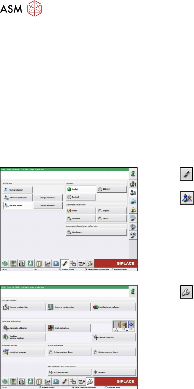
Fig.125: Select operator level
► Click the
button to enter the Settings
menu.
► Click the
button to open the Check and set
user settings menu.
► Switch over to the operator level Machine ser-
vice.
Fig.126: Service Menu
► Click the
button to enter the Service menu.
► Click the Automatic calibration button.