ASM贴片机 X 系列机型电路图.pdf - 第71页
2 - 1 2 Wirkschaltpläne / Det ailed circuit diagrams NH-090 101LD3 NOTHALT -Schleife , S t romver sorgung ( Bl. 1 v . 5 ) Emergency- stop loop, power su pply (sh. 1 of 5) Voltag eConveyo r(+) 13 14 To PCB c onve yor, 003…
2 - viii
Wirkschaltplanmappe SIPLACE X-Serie / SIPLACE X-Series Detailed Circuit Diagrams Folder
Ausgabe 02/2011 DE/EN Edition
2 - 1
2 Wirkschaltpläne / Detailed circuit diagrams
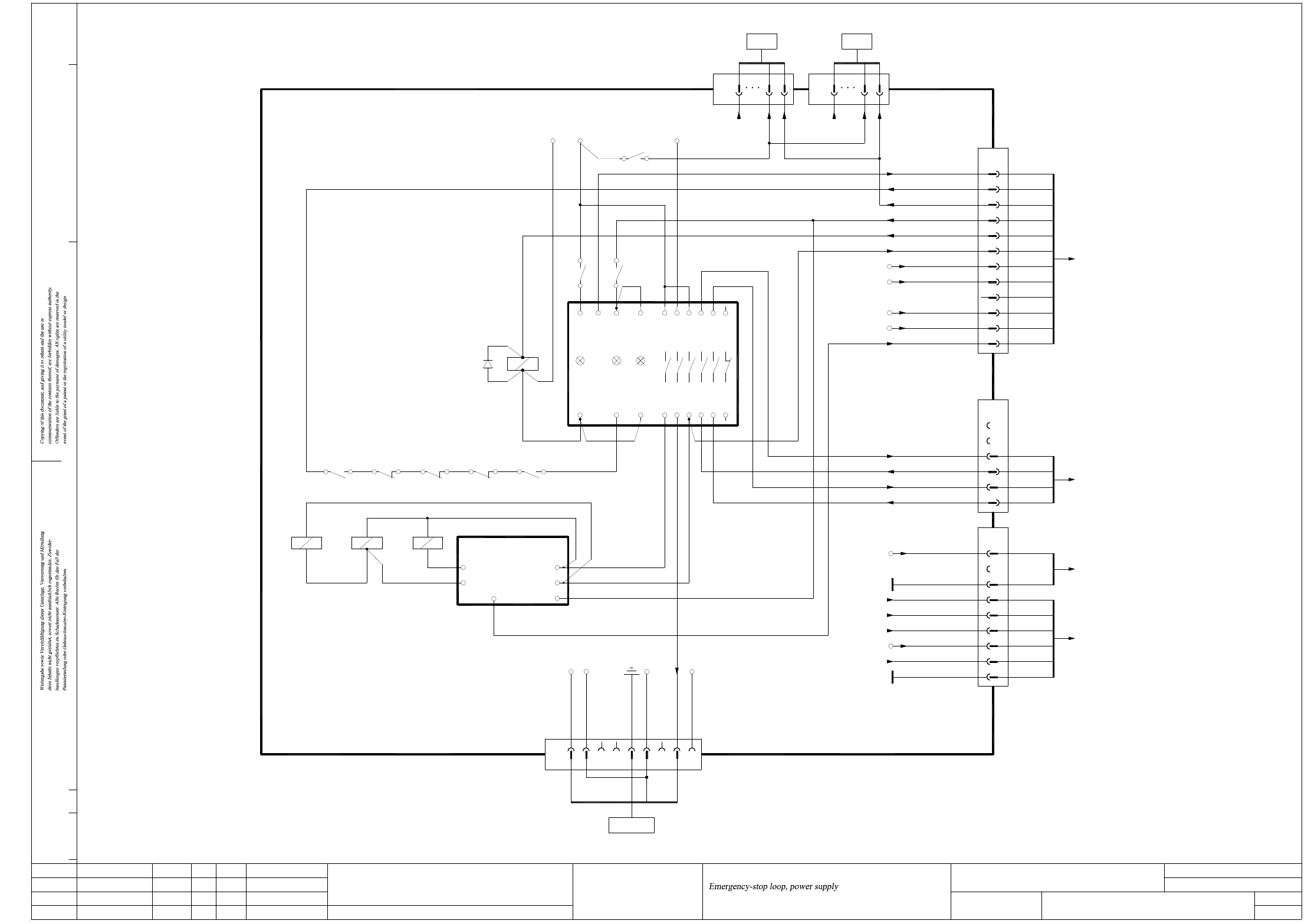
NH-090101LD3 NOTHALT-Schleife, Stromversorgung (Bl. 1 v. 5)
Emergency-stop loop, power supply (sh. 1 of 5)
VoltageConveyor(+)
13
14
To PCB conveyor, 00365546-W1
X15
31
X79
BK 2
4
3
GNYE
03002504
16
5
7
2
X7-10
X7-11
00354626
Power supply unit
A1(+)
A1(+)
K2
A2(-)
A2(-)
43
A1(+)
K4K3
A2(-)
212 1
+24V2
n.u.
GND(+24V2)
n.u.
VoltageConveyor(-)
n.u.
EmergencyStopLoopOK
X20:30
X20:40
U5(-)
servo
limiter,
Inrush current
ILS
X8-23
X8-21
X7-13
X7-12
6
1 5
EmergencyStopLoopEnd
S_TapeCutter
S_XY
Contactor relay blocks
K1.4 K2.4 K3.4
X5X3X1L+
A2 (-)
K4.4 K5
A1 (+)
V51
K5
X4L- X6
Channel1Power
supply
PCC K6
Channel2
42
K5
1
K5
3
GND(24)
X20:4
+24V
X20:3
K4.5
4
3
9
82
GND_P
GND_P
X16:11
X16:10
VoltageConveyor_Mot(+)
VoltageConveyor(+)
F8
+24V
GND (+5V)
GND (+24V)
Vin(-)Illumination
Vin(+)Illumination
F12
X16:8
4
3
2
1
2
7
8
9
6
5
(W5)
(W6)
(W5)
(W6)
(W6)
+5V
PCC54
PCC53
PCC44
Vin(-)Illumination
Vin(+)Illumination
n.u.
X16:7
F12
X18
1
2
1
4
3
1
2
(W6)
(W4)
(W4)
2
1
2
6
5
4
(W3)
(W3)
(W2)
(03046226)
To plug X3ra
sub-distributor
(sheet 4)
(03046225)
(03046225)
main distributor
To plug X3qa
(sheet 2)
03002506
To plug X3qa
main distributor
(sheet 2)
03002506
534333 6523
543424
44 66
PCC43
GND (+24V)
EmergencyStopLoopOK
n.u.
n.u.
X20_4
13
2
X17
1
(W2)
12
11
2 (W2)
GY (W4)
+5V
n.u.
StartButtonOn
S_GantryCrash
EmergencyStopLoopEnd
Software_CtrlOn
GND (+5V)
+24V
VoltageTapeCutter
X20_6
X20_3
X20_5
GN (W3)6
10
9
7
8
YE (W4)
1 (W2)
1 (W1)
2 (W1)
5
4
3
2
WH (W3)
BN (W3)
BN (W4)
GN (W4)
03050920 (W1+W2+W5)
X21
10
+34V
Servo Enable
03050900 (W1+W2+W5)
To axis unit 1
X13
1
X14
12
1
10
X31
S_Ready
To axis unit 2
12
X16
1WH (W4)
(03046225)
03002505
main distributor
To plug X2qa
(sheet 2)
09.
01.
01.
Status
Function status
Revision status
Document status
Modified Date Name
Date
Author
Check.
Stand.
Mat.no.:
CAD file:
Orig./Repl.f./Repl.by
Sh.
Sh.(s)
17.02.11
17.02.11
17.02.11
26.11.2007TDH
TDH
TDH
TDH
NH-090101LD3_SH01.DWG
Copyright ©
ASM Assembly Systems
GmbH & Co. KG
NOTHALT-Schleife, Stromversorgung
SIPLACE X2/X3/X4/X4I
SIPLACE X-Series
NH-090101LD3
1
5
2 - 2
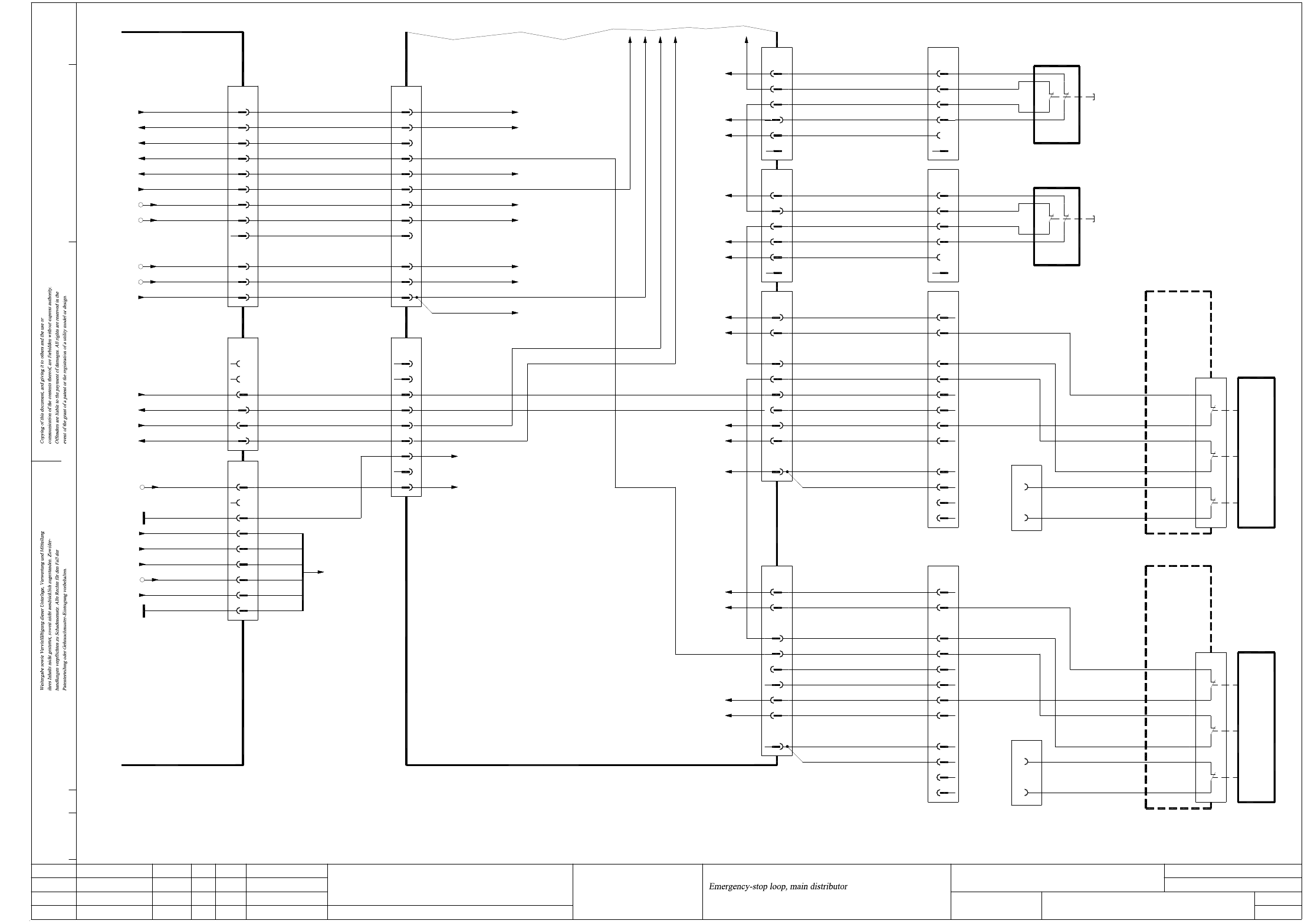
NH-090101LD3 NOTHALT-Schleife, Hauptverteiler (Bl. 2 v. 5)
Emergency-stop loop, main distributor (sh. 2 of 5)
EmergencyStopLoopMTC2Out
EmergencyStopLoopMTC2In
S_EmergencyStopButtonMTC
X72qa_2_S_EmergencyStopButtonMTC BK 109
03002506
(W5)2Vin(-)Illumination 9
00354626
Power supply
(sheet 1)
GND_P
GND (+24V)
GND (+5V)
Vin(-)Illumination
Vin(+)Illumination
Vin(+)Illumination
X16:7
X16:11
F12
X16:8
X16:10
GND_P
F12
8
7
4
1
+24V 6
5
3
2
(W6)
(W5)
(W6)
(W6)
n.u.n.u.
2
3
+5V 4
2
1
11
X18
(W4)
(W6)
(W4)
03046225 (qa)
Main distributor
sub-distributor
X3ra
n.u.
9
8
GY
n.u.
X1qa_Vin(+) illumination
(sheet 3)
OG
X1qa_24V
X5qb_7 (DI22)
(sheet 3)
(sheet 3)
X1qa_M_Flap
76
7
8
9
n.u.
BK
BK
n.u.
10
9
8
3
5
4
n.u.
BK
BK
6
5
4
X1qa_0V
1
2
GND
+24V
WH
X23qa
2+3
GNYE+1
03002506
03002505
PCC53
PCC44
PCC54
PCC43
(W2)13
6 2
4
5
2
1
(W3)
(W2)
(W3)
n.u.
n.u.
2
22 12
03020409
WH+BN
GN+YE
1121
Location 2
Hood switch
(sheet 4)
(sheet 3)
(sheet 3)
(sheet 3)
09.
01.
01.
Status
Function status
Revision status
Document status
Modified Date Name
Date
Author
Check.
Stand.
Mat.no.:
CAD file:
Orig./Repl.f./Repl.by
Sh.
Sh.(s)
17.02.11
17.02.11
17.02.11
26.11.2007TDH
TDH
TDH
TDH
NH-090101LD3_SH02.DWG
Copyright ©
ASM Assembly Systems
GmbH & Co. KG
NOTHALT-Schleife, Hauptverteiler
SIPLACE X2/X3/X4/X4I
SIPLACE X-Series
NH-090101LD3
2
5
n.u.
X223
03063606-W2
WH (W2)
BN (W2)
11
BN (W2)
WH (W2)
03063606-W2
X233
n.u.
S1
11
12
Component trolley
SIPLACE X-Series
docking unit
Location 3
1
X133
WH (W1)
YE (W1)
GN (W1)
BN (W1)
n.u.
n.u.
n.u.
2
4
3
6
7
8
5
n.u.
03063606-W1
21
31
22
32
n.u.
n.u.
n.u.
10
12
n.u.
11
n.u.
9
Component trolley
SIPLACE X-Series, location 3
11
X1qa_StartButton
CAN I/O module
X19qa_4
(sheet 3)
(sheet 3)
X1qa_0V
X1qa_24V
X73qa_9
(sheet 3)
X71qa_6
X72qa_4
X72qa_3
BK GY+PK
5
4
6
n.u.
GND
WH
BK
n.u.
BU
RD
1
2
3
OG
+24V
BK
(sheet 3)
X12qa_3
WH+BN
GN+YE
X13qa
SIPLACE X-Series, location 2
Component trolley
9
+24V
S_Flap
S_COTable3
EmergencyStopLoopIn
EmergencyStopLoopOut
GND
03002535
n.u.
11
n.u.
12
10
n.u.
n.u.
n.u.
32
22
31
21
X53
03063606-W1
n.u.
5
S_Flap
S_COTable2
8
7
6
EmergencyStopLoopOut
EmergencyStopLoopIn
+24V
3
4
2
n.u.
n.u.
n.u.
BN (W1)
GN (W1)
YE (W1)
(W1)WH
03002531
GND
GND
X123
1
n.u.
6
5
EmergencyStopLoopIn
EmergencyStopLoopOut
S_Hood3
+24V
4
3
1
2
n.u.
n.u.
GY+PK
BU
WH+BN
GN+YE
22 12
21 11
Location 2
docking unit
SIPLACE X-Series
Component trolley
12
11
S1
Hood switch
Location 3
EmergencyStopLoopOut
03002528-W1
S_Hood2
GND
n.u.
6
5
4
EmergencyStopLoopIn
+24V
03002527-W1
1
2
3
X52
GY+PK
03020409
n.u.
n.u.
BU
n.u.
n.u.
1
X17
EmergencyStopLoopOK
VoltageTapeCutter
GND (+5V)
GND (+24V)
X20:4
X20:3
X20:6
X20:5
GY (W4)12
11
10+24V
1 (W2)
2 (W2)
GN (W3)
YE (W4)
n.u. 9
8
+5V 7
6
2 (W1)
1 (W1)
S_Ready
StartButtonOn
S_GantryCrash
EmergencyStopLoopEnd
Software_CtrlOn
WH (W4)
BN (W4)
GN (W4)
WH (W3)
BN (W3)
3
4
5
2
1
X16
X1qa_Software_CtrlOn
X14qa
CAN I/O module
PCC54
PCC53
PCC44
PCC43
BK3
7
6
WH
BK
4
5
BK
BK
n.u.
n.u.
2
1
n.u.
n.u.
X3qa
X1qa_0V
EmergencyStopLoopOK
+24V
GND (+24V)
GND (+5V)
VoltageTapeCutter
12 BK
10
11
OG
WH
9
8
n.u.
WH
7
6
PK +5V
BK
X1qa_0V
X3qb_1 (DI0)
X1qa_24V
X1qa_0V
X1qa_5V
X1qa_0V
X5qb_3 (DI18)
(sheet 3)
(sheet 3)
X1qa_M_Flap
EmergencyStopLoopMTC2Out
EmergencyStopLoopMTC2In
X1qa_24V
BK
65
6
7
8
BK
BK
BK
9
8
7
3
2
4
BK
BK
+24V
OG
4
5
2+3
X24qa_4
(sheet 3)
(sheet 3)
X1qa_0V
X1qa_24V
1
6
5
GND
WH
GND
n.u.
WH
GNYE+1
X18qa
n.u.
RD
1
2
4
3
BK
BK
+24V
OG
BK
BU
GY+PK
WH+BN
GN+YE
Software_CtrlOn
EmergencyStopLoopEnd
StartButtonOn
S_Ready
n.u.
3
4
5
BK
BK
2
1
BK
BK
X2qa
X4qb_2 (DI9)