Operating Instructions_VF366_en.pdf - 第184页
6|Function description 6.9.10 Working with deflection measurement If your machine is equipped with deflection measurement, you can use this func- tion to automatically compensate for the printed circuit board deflectio…

6|Function description
ð The PCBs will only be fed into the module it the next module is empty. This
way, the PCBs are prevented, for example, from remaining too long in the
module due to a jam. However, this function can extend the cycle times.
Permanently fixing PCBs
ü To permanently fix PCBs during processing:
a) Activate the [Fix horizontal permanently] checkbox.
ð The PCBs are aligned in the module and then laterally fixed until processing is
completed. If the checkbox is not activated, the PCBs are only aligned and then
released again. You can activate this function separately for all available fluxer
and soldering modules
Manually compensating for the PCB deflection
Due to the heating and weight of the components, the PCBs get bent during pro-
cessing. Thereby, the distance [Z] from the solder nozzle to the soldering joint
changes. The machine corrects this error if an offset value is specified. The control-
ler takes into account the deflection and corrects the distances accordingly.
ü To compensate the [Board deflection] in machines without deflection measure-
ment:
a) Select the current soldering module from the [Data source] dropdown menu.
b) Determine the deflection of the board at the point of greatest deflection. This
is generally a point in the middle of the PCB.
c) Enter the deflection in [mm] into the [Correction] input field. Enter a positive
value if the board bends downwards. Enter a negative value if the board bends
upwards.
ð The deflection of the board is now taken into account by the controller and the
[Z] distances to the solder joints are corrected accordingly.
Click on
to close the dialog.
Ersa GmbH Operating Instructions_VF366_en|Rev. 14|30/11/2017 183/551

6|Function description
6.9.10 Working with deflection measurement
If your machine is equipped with deflection measurement, you can use this func-
tion to automatically compensate for the printed circuit board deflection. A sensor
reads the height [Z] in two pcb points. The controller uses said readings to calculate
the deflection and correct distances accordingly.
ü To set reference positions:
a) Enter a Reference position [X] and [Y] each time. The pcb should not deflect in
this position, and no component should be positioned on the lower side of the
pcb. This position should preferably be on the pcb edge.
b) Enter a Measuring position [X] and [Y] each time. In this position the pcb
should be deflecting at the most, no component should be positioned on the
lower side of the pcb.
c) Enable the [Use] checkbox.
ð Only the controller takes into account the pcb deflection. Before the actual sol-
dering process, the sensor compares the [Reference position] with the [Meas-
uring position] and determines the deflection. In this ways the machine cycle
time can be extended.
Click on
to close the dialog.
Ersa GmbH Operating Instructions_VF366_en|Rev. 14|30/11/2017 184/551
6|Function description
6.9.11 Working with data sets
The [Set data] dialog contains all the necessary data for the manufacturing process.
Creating data sets in the [Set data] dialog
ü To create data sets:
a) Open the [General soldering program data] dialog.
b) Click on the
button in the corresponding module below level 6.
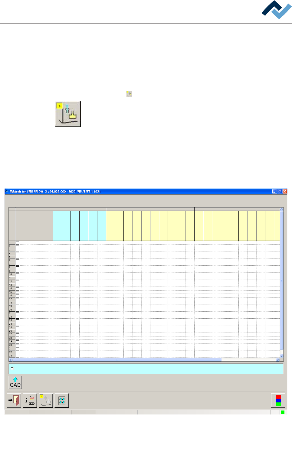
Open the [Set data] dialog. In this dialog, you can create your soldering program. It
contains target coordinates for fluxer and soldering modules, travel speeds and in-
formation regarding the solder wave height. The yellow square provides informa-
tion about how often the dialog has already been opened.
Data sets
A soldering program can contain an unlimited number of data sets. If the number
of data sets exceeds 15, a new data set is created automatically at the bottom end
of the table. Use the scroll bar at the right edge of the window to scroll through the
window and view all data sets.
Soldering program editor
user:
ersa
Maintenance mode
Set data
Set data
Set
Hide
Description
Endposition X [mm]
Endposition Y [mm]
Speed X/Y [mm/s]
mode
Spray amount [%]
Spray time [s]
Flux unit Soldering unit 1
Z while moving [mm]
Endposition X [mm]
Endposition Y [mm]
Speed X/Y [mm/s]
Endposition Z [mm]
Speed Z [mm/s]
Wave height [%]
Soldering time [s]
Lower value [%]
Lowering time [s]
Soldering unit 2
Z while moving [mm]
Endposition X [mm]
Endposition Y [mm]
Speed X/Y [mm/s]
Endposition Z [mm]
Speed Z [mm/s]
Wave height [%]
Soldering time [s]
Lower value [%]
Lowering time [s]
Fluxer coordinates relate to nozzle 1
Fig.41: Data sets with individual registers
Ersa GmbH Operating Instructions_VF366_en|Rev. 14|30/11/2017 185/551