00198608-02_SM_CP20P2_Kunde_EN.pdf - 第18页
3 Component camera, Z axis and component sensor 3.2 Replacing the component camera cable 18 Service Manual SIPLACE SpeedStar (C&P20 P2) 01/2019 3.2 Replacing the component camera cable Parts 03112088-xx Cable VHI - V…
3 Component camera, Z axis and component sensor
3.1 Replacing the Component Camera
Service Manual SIPLACE SpeedStar (C&P20 P2) 01/2019 17
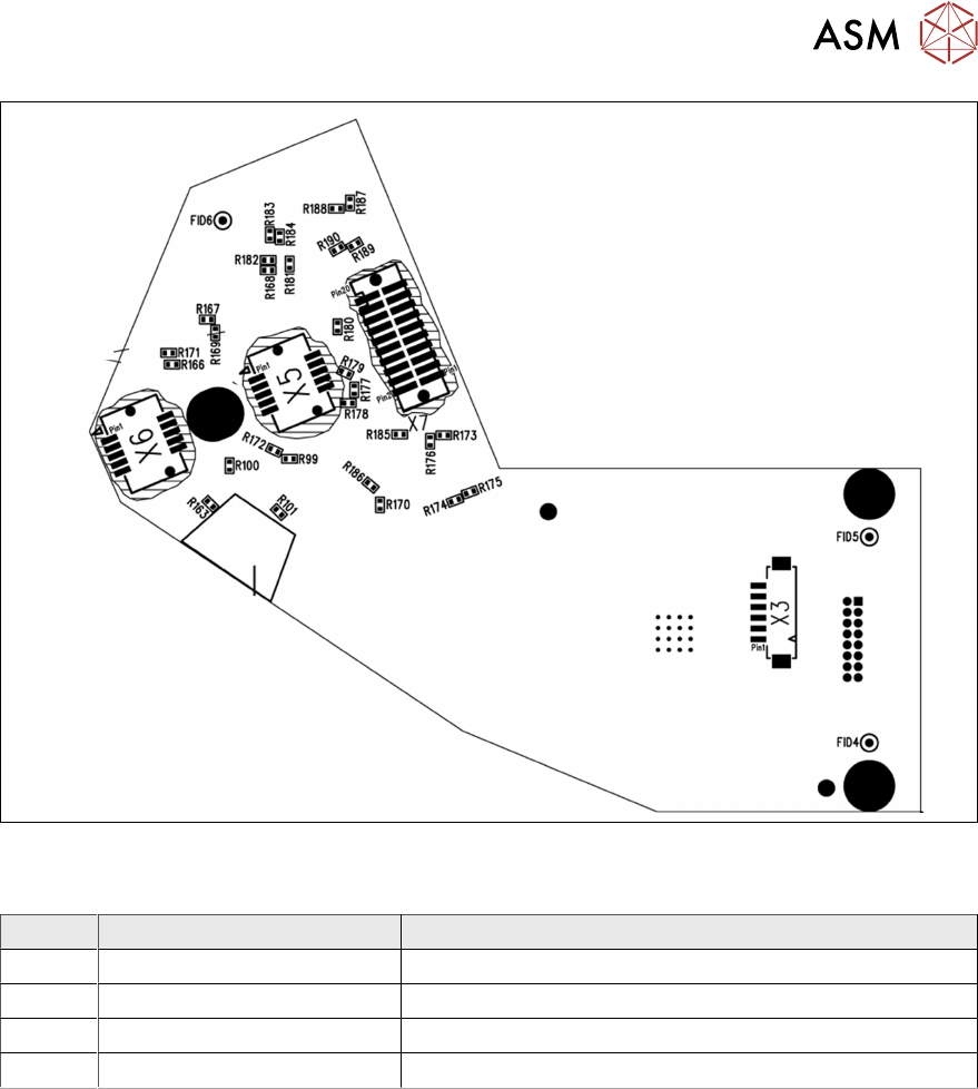
Fig.11: Camera type 48 – board back
LEDs [03146613-02]
LED Color Description
H1 Green 24V
H2 Green 42V
H62 Red Error
H63 Green, flashes Run
3 Component camera, Z axis and component sensor
3.2 Replacing the component camera cable
18 Service Manual SIPLACE SpeedStar (C&P20 P2) 01/2019
3.2 Replacing the component camera cable
Parts
03112088-xx Cable VHI - VLC41 GigE
The second camera cable is fixed to the component camera. In the event of service work, you will
need to replace the whole component camera.
Equipment and tools
T07 03078400-xx Torque Screwdriver ESD 1.0-5.0 Nm
T19 00318673-xx Wire cutter electronic size 110
T78 03090019-xx Torque interchangeable blades 2.5 mm, hexagonal
C08 00308458-xx Cable ties B=2.5mm, L=102mm Panduit
T --- Tools for removing/fitting and calibrating the placement head, if needed
(see also the service manual for your machine)
Preparation
► Remove the head from the machine. For details about removing and fitting the placement
head, refer to the service manual for your machine.
Fit the head on the head mount [03056231‑xx].
CAUTION
Do not damage or contaminate the camera lens system.
► Make sure that you do not damage or contaminate the camera lens system.
► Make sure that the component sensor protective cap is fitted.
1.1.3 "Safety instructions for the component sensor" [}6]
Removal
► Dismantle the component camera.
3.1 "Replacing the Component Camera" [}13]
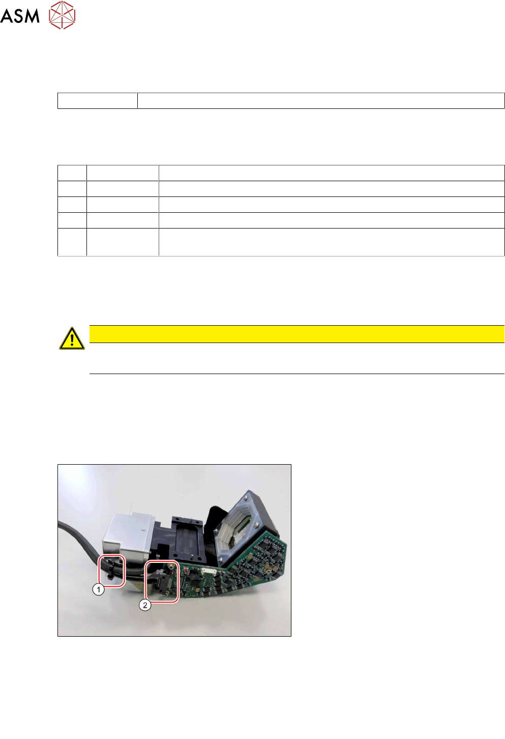
Fig.12: Loosening the cable
► Open the cable ties(1).
► Unlock the connectors(2) on both
sides and then remove the cable.
Installation
► Follow the removal instructions in reverse order for installation.
Also observe the installation instructions in the following section:
3.1 "Replacing the Component Camera" [}13]
► Observe in particular the torques specified!
3 Component camera, Z axis and component sensor
3.3 Replacing the Z axis cover
Service Manual SIPLACE SpeedStar (C&P20 P2) 01/2019 19
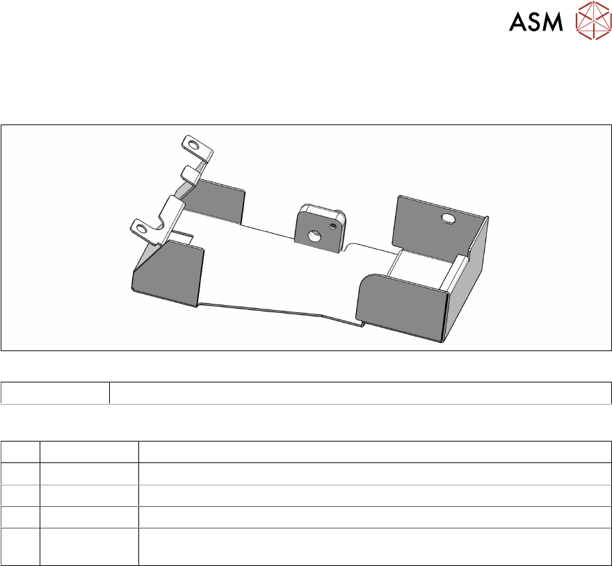
3.3 Replacing the Z axis cover
Parts
Fig.13: Z axis cover
03146048Sxx Bottom cover assembly C&P20P2
Equipment and tools
T07 03078400-xx Torque Screwdriver ESD 1.0-5.0 Nm
T47 00386253-xx Torque screwdriver ESD 0.4-1.0 Nm
T97 03075862-xx Torque Allen swap blade 1.5 mm TX8
T98 03171857-xx Torque Allen swap blade 1.5 mm TX10
T --- Tools for removing/fitting and calibrating the placement head, if needed
(see also the service manual for your machine)
Preparation
► Remove the head from the machine. For details about removing and fitting the placement
head, refer to the service manual for your machine.
Fit the head on the head mount [03056231‑xx].