00198608-02_SM_CP20P2_Kunde_EN.pdf - 第23页
3 Component camera, Z axis and component sensor 3.4 Replacing the round magnets Service Manual SIPLACE SpeedStar (C&P20 P2) 01/2019 23 Fig.20: Flexible mounting plate The flexible mounting plate can now be ac- cesse…
3 Component camera, Z axis and component sensor
3.4 Replacing the round magnets
22 Service Manual SIPLACE SpeedStar (C&P20 P2) 01/2019
3.4 Replacing the round magnets
Parts
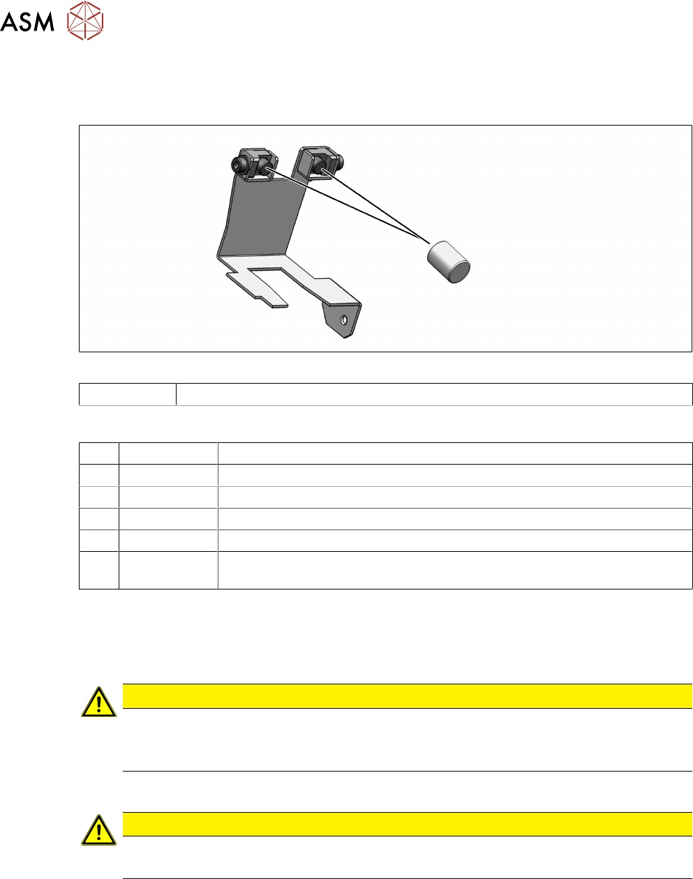
Fig.19: Round magnets on the flexible mounting plate
00349527-xx Round magnet 3x4 neodymium
Equipment and tools
T07 03078400-xx Torque Screwdriver ESD 1.0-5.0 Nm
T45 03078491-xx Magnet removal plate C&P20A
T47 00386253-xx Torque screwdriver ESD 0.4-1.0 Nm
T97 03075862-xx Torque Allen swap blade 1.5 mm TX8
T98 03171857-xx Torque Allen swap blade 1.5 mm TX10
T --- Tools for removing/fitting and calibrating the placement head, if needed
(see also the service manual for your machine)
Preparation
► Remove the head from the machine. For details about removing and fitting the placement
head, refer to the service manual for your machine.
Fit the head on the head mount [03056231‑xx].
CAUTION
Sensitive lenses
The transmitter and receiver unit lenses on the component sensor are highly sensitive.
► Make sure that you do not damage or contaminate the lens system.
Removal
CAUTION
Place the head vertically
► Place the head vertically so that no screws can fall into the Z axis
► Dismantle the Z axis cover.
3.3 "Replacing the Z axis cover" [}19]
3 Component camera, Z axis and component sensor
3.4 Replacing the round magnets
Service Manual SIPLACE SpeedStar (C&P20 P2) 01/2019 23
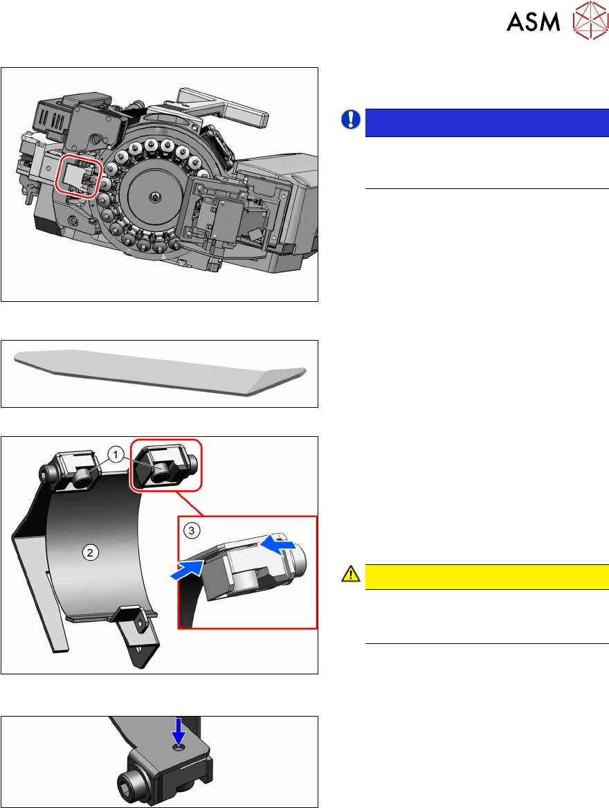
Fig.20: Flexible mounting plate
The flexible mounting plate can now be ac-
cessed.
NOTICE!
You do NOT need to dismantle the
flexible mounting plate to replace the
round magnets.
.
Fig.21: Magnet removal plate
Fig.22: Magnets in the flexible mounting plate (shown
without the rest of the head)
Fig.23: Opening at the top
► Carefully pull the flexible mounting
plate slightly out of the head and
remove the two round magnets(1) with
the magnet removal plate.
Alternatively, you could use tweezers.
If the two round magnets are stuck, proceed
as follows:
Stuck round magnets
► If the round magnets are stuck, you can
carefully press these up through the
opening at the top.
CAUTION!
Cover flex
Take care not to damage the cover
flex.
.
The cover flex(2) is held by the round mag-
nets in the slits(3).
► If the cover flex is damaged, you will need to replace it.
3.6 "Replacing the cover flex" [}27]
3 Component camera, Z axis and component sensor
3.5 Replacing the flexible mounting plate
24 Service Manual SIPLACE SpeedStar (C&P20 P2) 01/2019
Installation
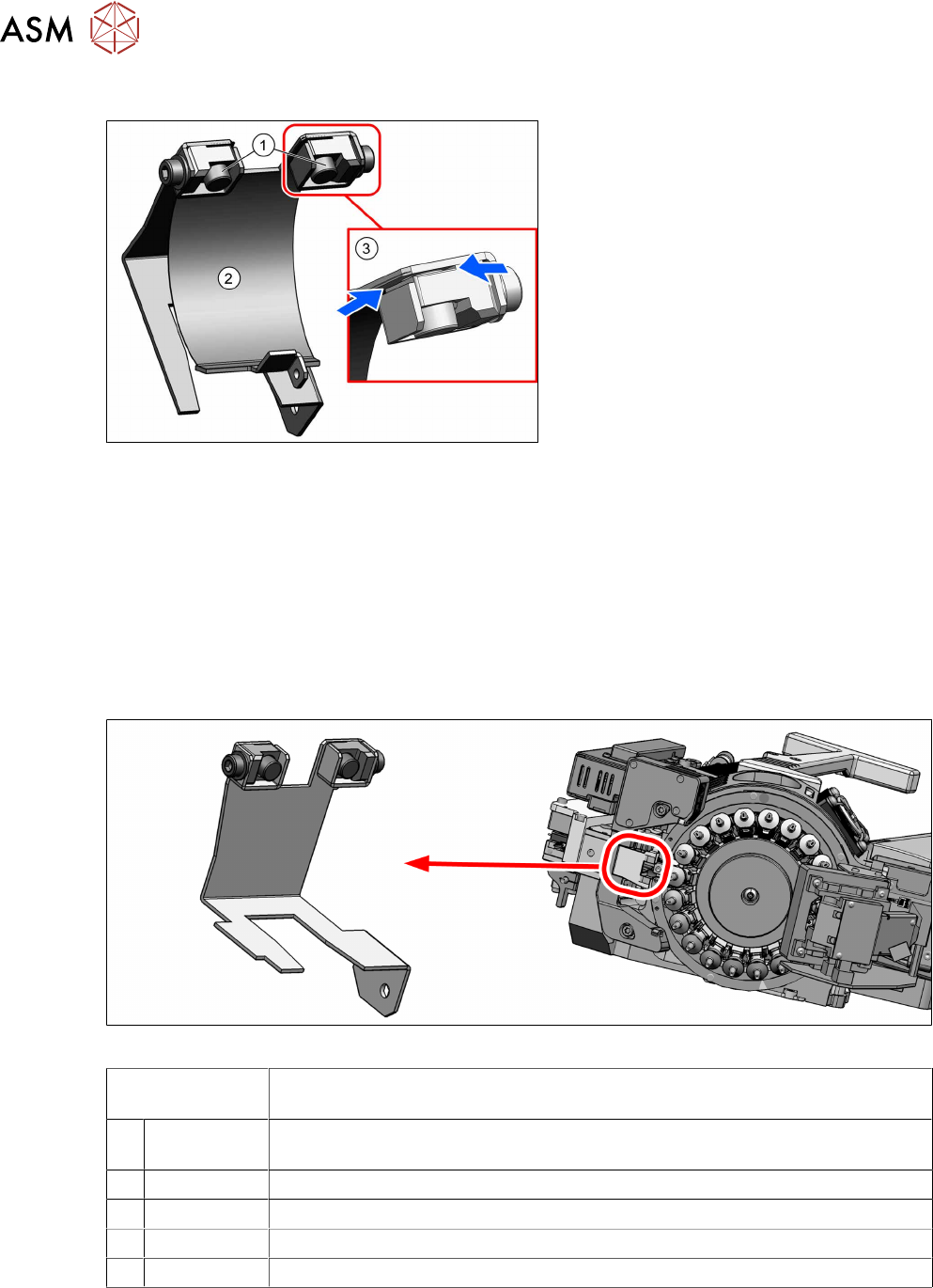
Fig.24: Inserting the magnets (shown without the rest of the
head)
► Make sure that the two ends of the
cover flex(2) are inserted properly into
the slits(3).
► Fasten the cover flex with the two
round magnets(1).
► Follow the removal instructions in reverse order for further installation.
Also observe the installation instructions in the following section:
3.3 "Replacing the Z axis cover" [}19]
► Observe in particular the torques specified!
3.5 Replacing the flexible mounting plate
Parts
Fig.25: Flexible mounting plate assembly on the SIPLACE C&P20P2
03146046Sxx
Consists of:
Flexible mounting plate assembly, C&P20 P2
2 00349527-xx Round magnet 3x4 neodymium
Can also be replaced individually: 3.4 "Replacing the round magnets" [}22]
2 03077829-xx Magnet support / C+P20A
1 03146266-xx Cover plate, inside CP20 P2
2 03100630-xx ISO 7089 - 1.6 - 200 HV - A2
2 03042514-xx ISO 4762 - M 1.6 x 3-A2-70