00198608-02_SM_CP20P2_Kunde_EN.pdf - 第27页
3 Component camera, Z axis and component sensor 3.6 Replacing the cover flex Service Manual SIPLACE SpeedStar (C&P20 P2) 01/2019 27 3.6 Replacing the cover flex CAUTION Sensitive lenses The transmitter and receiver u…
3 Component camera, Z axis and component sensor
3.5 Replacing the flexible mounting plate
26 Service Manual SIPLACE SpeedStar (C&P20 P2) 01/2019
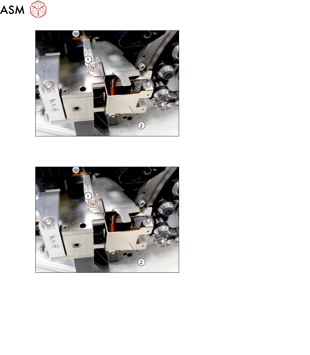
Fig.26: Dismantling the flexible mounting plate
► Remove the fastening screw (1).
► Carefully pull the flexible mounting
plate(2) out of the head.
Installation
Fig.27: Fitting the flexible mounting plate
► Carefully insert the flexible mounting
plate(2) and fasten this with a
screw(1) (M1.6x3, torque 0.2Nm).
► Follow the removal instructions in reverse order for further installation.
Also observe the installation instructions in the following sections:
3.4 "Replacing the round magnets" [}22]
5.2 "Replacing the pressure control valve (PRV)" [}41]
5.1 "Replacing the support plate on the PRV" [}39]
3.7 "Replacing the component sensor" [}30]
3.3 "Replacing the Z axis cover" [}19]
► Observe in particular the torques specified!
3 Component camera, Z axis and component sensor
3.6 Replacing the cover flex
Service Manual SIPLACE SpeedStar (C&P20 P2) 01/2019 27
3.6 Replacing the cover flex
CAUTION
Sensitive lenses
The transmitter and receiver unit lenses on the component sensor are highly sensitive.
► Make sure that you do not damage or contaminate the lens system.
Parts
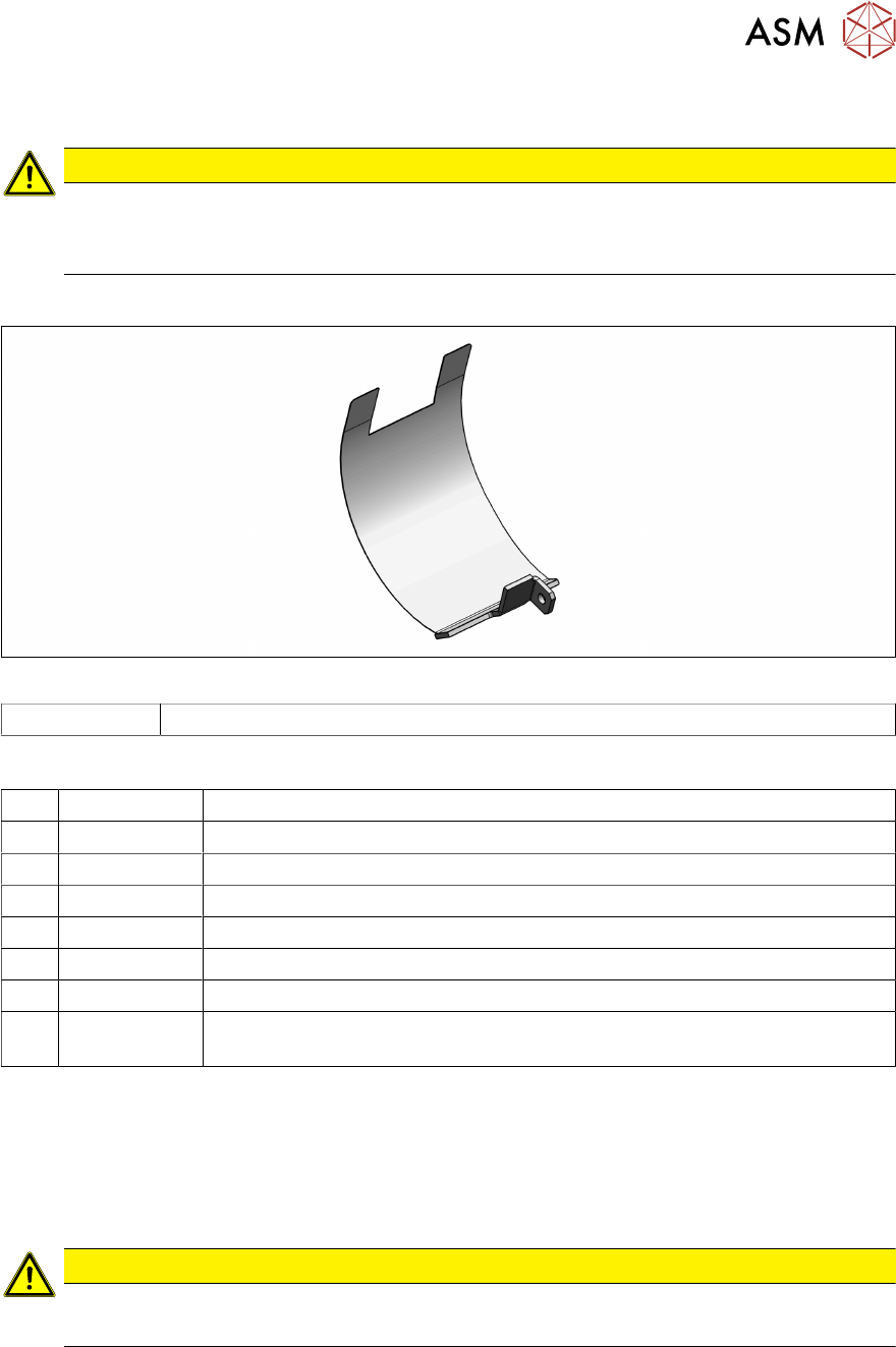
Fig.28: Cover flex
03077368‑xx Cover flex assembly SIPLACE C&P20A
Equipment and tools
T07 03078400-xx Torque Screwdriver ESD 1.0-5.0 Nm
T45 03078491-xx Magnet removal plate C&P20A
T47 00386253-xx Torque screwdriver ESD 0.4-1.0 Nm
T97 03075862-xx Torque Allen swap blade 1.5 mm TX8
T98 03171857-xx Torque Allen swap blade 1.5 mm TX10
T99 03171856-xx Torque Allen swap blade 1.5 mm TX20
T --- Tweezers
T --- Tools for removing/fitting and calibrating the placement head, if needed
(see also the service manual for your machine)
Preparation
► Remove the head from the machine. For details about removing and fitting the placement
head, refer to the service manual for your machine.
Fit the head on the head mount [03056231‑xx].
Removal
CAUTION
Hold the head vertically
► Place the head vertically so that no screws can fall into the Z axis
► Dismantle the Z axis cover.
3.3 "Replacing the Z axis cover" [}19]
► Dismantle the component sensor.
3.7 "Replacing the component sensor" [}30]
► Dismantling the support plate on the PRV
5.1 "Replacing the support plate on the PRV" [}39]
3 Component camera, Z axis and component sensor
3.6 Replacing the cover flex
28 Service Manual SIPLACE SpeedStar (C&P20 P2) 01/2019
► Dismantle the pressure control valve.
5.2 "Replacing the pressure control valve (PRV)" [}41]
► Remove the two round magnets.
3.4 "Replacing the round magnets" [}22]
Fig.29: Flexible mounting plate
► Remove the fastening screw (1)(TX6).
► The flexible mounting plate(2) can now
be carefully pull out slightly.
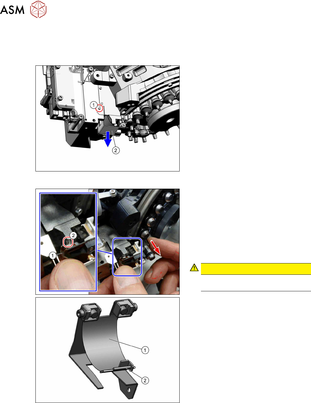
Fig.30: Screw fastening the cover flex
The cover flex(1) is fixed with a screw(2)
(DIN8243 A M1x8‑A2) and a clamping plate
to the head. Depending on the head version,
the clamping plate will be loose or fixed to
the frame.
► Carefully pull the Z axis on the DP drive
downwards.
► Remove the fastening screw(2) (slot-
ted screw) and the clamping plate.
CAUTION!
Take care not to lose the screw and
the clamping plate opposite to this.
.
► Carefully take the cover flex assem-
bly(1)out.