00198608-02_SM_CP20P2_Kunde_EN.pdf - 第32页
3 Component camera, Z axis and component sensor 3.7 Replacing the component sensor 32 Service Manual SIPLACE SpeedStar (C&P20 P2) 01/2019
3 Component camera, Z axis and component sensor
3.7 Replacing the component sensor
Service Manual SIPLACE SpeedStar (C&P20 P2) 01/2019 31
Removal
► Dismantle the Z axis cover.
3.3 "Replacing the Z axis cover" [}19]
You can now access the component sensor.
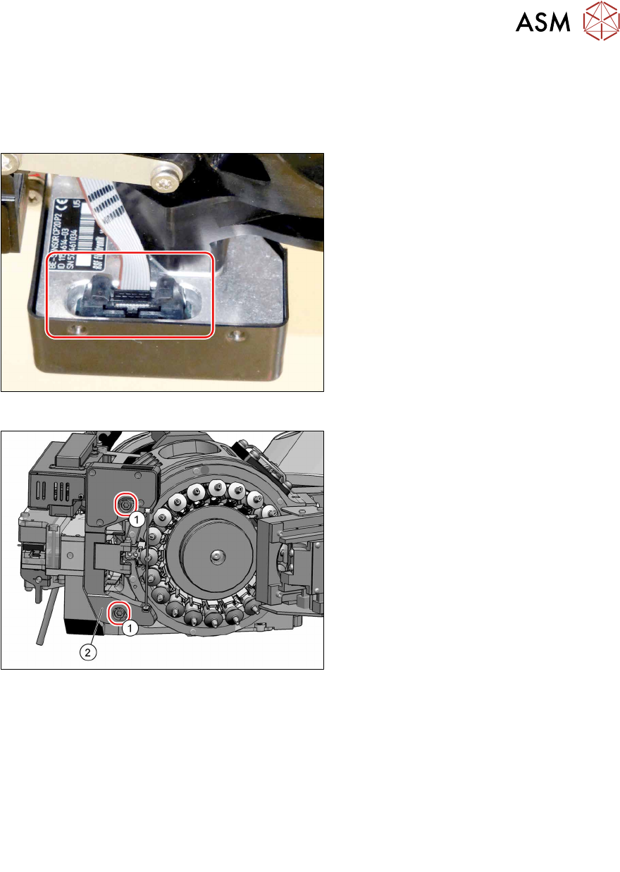
Fig.33: Electrical connection
► Unplug the electrical connection from
the component sensor.
Remove any cable ties if needed. You
may want to mark their positions for
easier exact replacement later on.
Fig.34: Fastening screws
► Remove the two screws(1) (TX20)
fastening the component sensor(2)
and then remove the component
sensor.
Installation
► Fix the new component sensor into place with the two fastening screws (TX20, torque:
1.9Nm) and washers.
► Plug in the electrical connection. Fasten the cable with cable ties, if required.
► Follow the removal instructions in reverse order for further installation.
Also observe the installation instructions in the following section:
3.3 "Replacing the Z axis cover" [}19]
► Observe in particular the torques specified!
► Calibrate the component sensor after installation.

3 Component camera, Z axis and component sensor
3.7 Replacing the component sensor
32 Service Manual SIPLACE SpeedStar (C&P20 P2) 01/2019
4 DP drives
4.1 Replacing the clamping plate at the DP drive
Service Manual SIPLACE SpeedStar (C&P20 P2) 01/2019 33
4 DP drives
4.1 Replacing the clamping plate at the DP drive
Parts
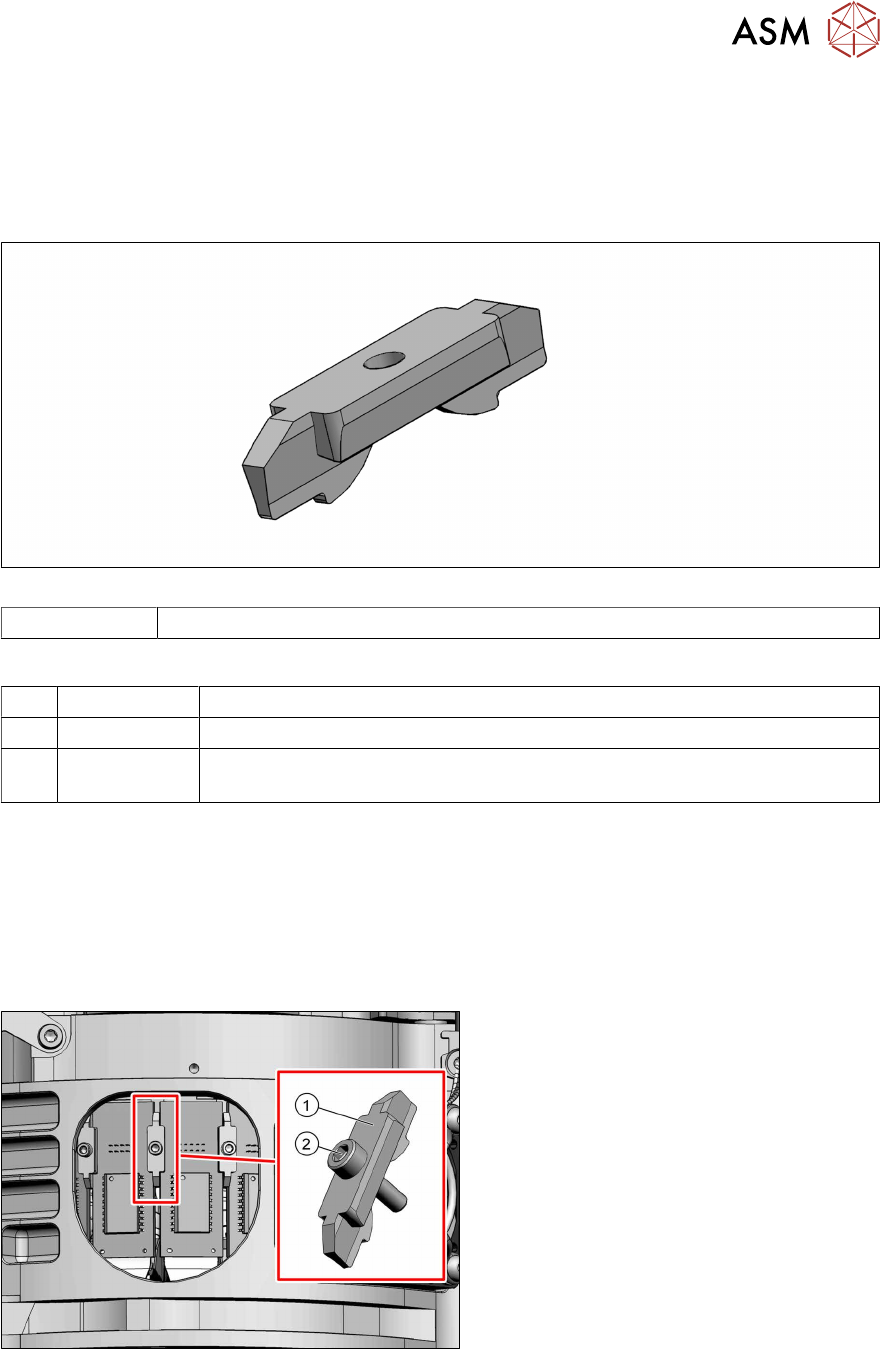
Fig.35: Clamping plate
03005144‑xx Clamping plate
Equipment and tools
T44 00386132-xx Torque screwdriver ESD 0.1-0,6 Nm
T76 00386135-xx Torque interchangeable blades 1.5 mm, hexagonal
T --- Tools for removing/fitting and calibrating the placement head, if needed
(see also the service manual for your machine)
Preparation
► Remove the head from the machine. For details about removing and fitting the placement
head, refer to the service manual for your machine.
Fit the head on the head mount [03056231‑xx].
► Make sure that the component sensor protective cap is fitted.
1.1.3 "Safety instructions for the component sensor" [}6]
Removal
Fig.36: Clamping plate
► Remove the fastening screw(2)
(Allen1.5) and then remove the clamp-
ing plate(1).
Installation
► Fit the new clamping plate. Tighten the screw fastening the clamping plate with a torque of
0.1 Nm.