00198608-02_SM_CP20P2_Kunde_EN.pdf - 第38页
4 DP drives 4.2 Replacing the DP drive and hose 38 Service Manual SIPLACE SpeedStar (C&P20 P2) 01/2019 Fig.46: DP drive (example of SIPLACE C&P20P shown) ► Use the service opening to insert the new DP drive int…
4 DP drives
4.2 Replacing the DP drive and hose
Service Manual SIPLACE SpeedStar (C&P20 P2) 01/2019 37
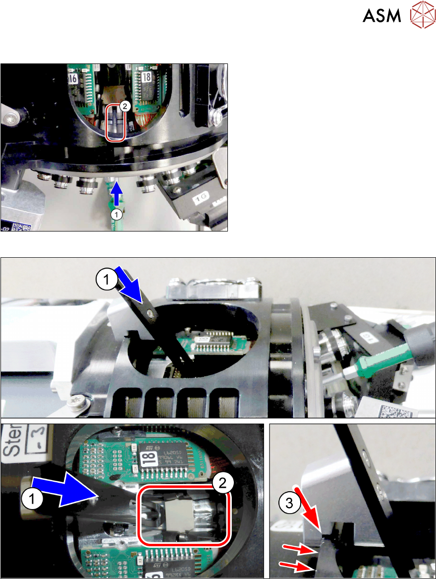
Fitting the DP drive
Fig.44: Spring pin
► Carefully push the spring pint(2) back
with a Torx screwdriver (1).
Fig.45: Inserting the DP change tool
► (1) Insert the DP change tool.
(2) The spring pin is held by the DP change tool. This spring pin is not directly visible.
(3) Pay attention to the correct fit of the DP change tool on the head. The bottom notch on the
DP change tool must be on the edge.
4 DP drives
4.2 Replacing the DP drive and hose
38 Service Manual SIPLACE SpeedStar (C&P20 P2) 01/2019
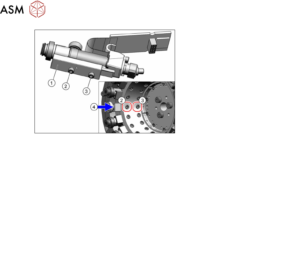
Fig.46: DP drive (example of SIPLACE C&P20P shown)
► Use the service opening to insert the
new DP drive into the head. Position
the linear guide (1) on the star carrier.
► Loosely fix the linear guide with a new
fastening screw (3).
► (4) Press the linear guide towards the
spring pin.
► Tighten the two new fastening
screws(3) and(2) (Allen1.5) with a
torque of 0.2Nm.
► Remove the DP change tool.
► Check that the spring unit is correctly seated. To do this, press the DP drive inwards. This
should easy to do.
► Use the tweezers to fit the hose onto the DP drive.
Make sure that you only use the "blunt tweezers 145mm size 3mm" [00376493‑xx].
Take care that the hose is not bent or damaged.
Do not twist the hose when connecting it.
► Make sure that the DP drive can be compressed upwards.
► Press the board into the connector.
► Follow the removal instructions in reverse order for further installation.
Also observe the installation instructions in the following sections:
4.1 "Replacing the clamping plate at the DP drive" [}33]
6.1 "Replacing the aperture ring/holding circuit/sealing disc" [}45]
► Observe in particular the torques specified!
5 Pressure control valve (PRV)
5.1 Replacing the support plate on the PRV
Service Manual SIPLACE SpeedStar (C&P20 P2) 01/2019 39
5 Pressure control valve (PRV)
5.1 Replacing the support plate on the PRV
Parts
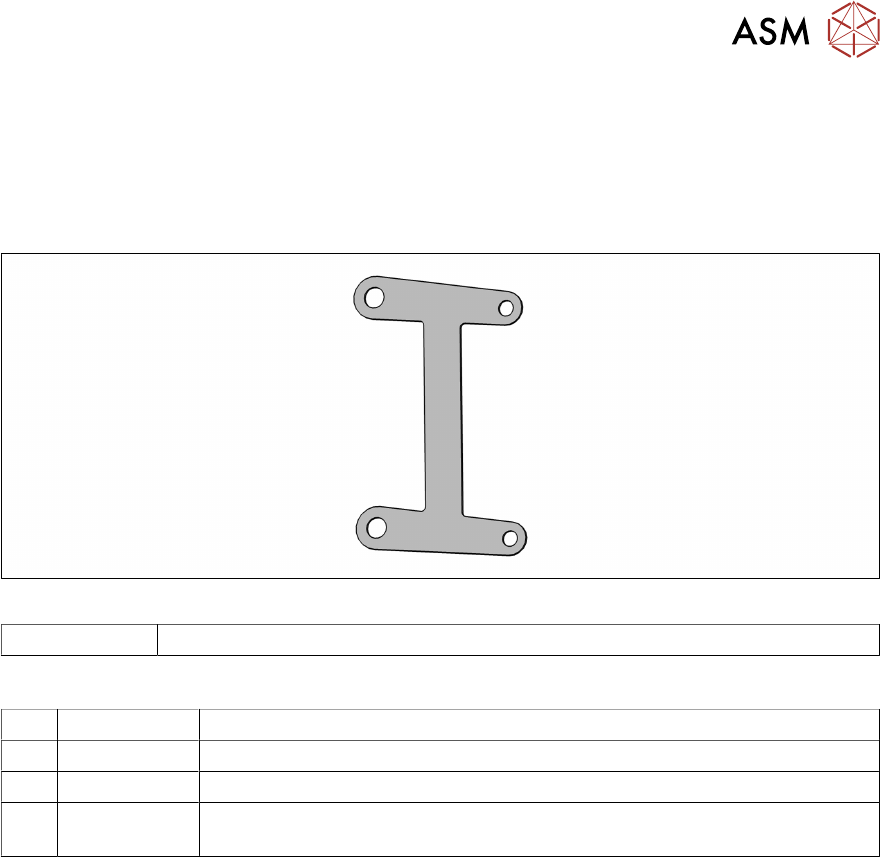
Fig.47: Support plate
03154883-xx Support plate for pneumatic valve C&P20P2
Equipment and tools
T47 00386253-xx Torque screwdriver ESD 0.4-1.0 Nm
T98 03171857-xx Torque Allen swap blade 1.5 mm TX10
T99 03171856-xx Torque Allen swap blade 1.5 mm TX20
T --- Tools for removing/fitting and calibrating the placement head, if needed
(see also the service manual for your machine)
Preparation
► Remove the head from the machine. For details about removing and fitting the placement
head, refer to the service manual for your machine.
Fit the head on the head mount [03056231‑xx].
► Make sure that the component sensor protective cap is fitted.
1.1.3 "Safety instructions for the component sensor" [}6]