00198608-02_SM_CP20P2_Kunde_EN.pdf - 第4页
4 Service Manual SIPLACE SpeedStar (C&P20 P2) 01/2019 Contents 6 Aperture ring, holding circuit and silencer .. 45 6.1 Replacing the aperture ring/holding circuit/sealing disc .. 45 6.2 Replacing the silencer (ve…

3Service Manual SIPLACE SpeedStar (C&P20 P2) 01/2019
Contents
Contents
1 Introduction.. 5
1.1 Safety instructions.. 5
1.1.1 Conventions for the use of safety instructions and symbols.. 5
1.1.2 Safety instructions on hazardous materials.. 6
1.1.3 Safety instructions for the component sensor.. 6
1.2 Other instructions.. 6
1.2.1 Environmentally-friendly disposal of materials and components.. 6
1.2.2 Use of original accessories and spare parts.. 6
1.2.3 Information about this service manual.. 6
1.2.4 ESD guidelines.. 7
1.2.4.1 What does ESD mean?.. 7
1.2.4.2 Important measures to protect against static charging.. 7
1.2.4.3 Handling ESD modules.. 7
1.2.4.4 Measurements and modifications to ESD modules.. 7
1.2.4.5 Dispatching ESD modules.. 8
1.2.5 Validity of Document.. 8
1.2.6 Release History.. 8
1.2.7 ASM on the World Wide Web (WWW).. 8
1.3 Staff qualifications and training.. 9
1.4 Abbreviations.. 9
2 Overview of the Modules.. 11
2.1 Overview of C&P20 P2 parts.. 11
2.2 Overview of torques and tools required.. 12
3 Component camera, Z axis and component sensor.. 13
3.1 Replacing the Component Camera.. 13
3.1.1 Board: Vision LED controller VLC48.. 16
3.2 Replacing the component camera cable.. 18
3.3 Replacing the Z axis cover.. 19
3.4 Replacing the round magnets.. 22
3.5 Replacing the flexible mounting plate.. 24
3.6 Replacing the cover flex.. 27
3.7 Replacing the component sensor.. 30
4 DP drives.. 33
4.1 Replacing the clamping plate at the DP drive.. 33
4.2 Replacing the DP drive and hose.. 34
5 Pressure control valve (PRV).. 39
5.1 Replacing the support plate on the PRV.. 39
5.2 Replacing the pressure control valve (PRV).. 41
5.3 Replacing the exhaust air hose.. 43

4 Service Manual SIPLACE SpeedStar (C&P20 P2) 01/2019
Contents
6 Aperture ring, holding circuit and silencer.. 45
6.1 Replacing the aperture ring/holding circuit/sealing disc.. 45
6.2 Replacing the silencer (venturi mode only).. 50
6.3 Replacing the holding circuit hose.. 51
6.4 Replacing the placement circuit hose.. 53
7 Screwed joint.. 55
7.1 Replacing the cover cap and grommet.. 55
7.2 Replacing the screwed joint.. 57
8 Return unit.. 61
8.1 Replacing the return unit, cylinder, holder and driver lever.. 61
9 Boards.. 67
9.1 Replacing the intermediate distributor board (ID).. 67
9.2 Intermediate distributor board for SIPLACE C&P20P2.. 70
9.3 Replacing the holding circuit board.. 71
10 Miscellaneous (fan, retaining elements).. 75
10.1 Replacing the fan.. 75
10.2 Replacing the retaining element mount and mount.. 78
11 Software functions.. 81
11.1 Calibration.. 81
11.1.1 Calibration procedure.. 81
11.1.2 Calibrating the heads and cameras (SW7x).. 82
11.2 Zero point correction for the star and Z axis.. 85
11.2.1 Transferring the head specific data (from SW701).. 85
11.3 Optical Nozzle Query (Nozzle Scanning).. 86
11.4 Calibrating the digital PRV.. 86
11.5 Zero Point Calibration of Pressure Control Valve.. 86
1 Introduction
1.1 Safety instructions
Service Manual SIPLACE SpeedStar (C&P20 P2) 01/2019 5
1 Introduction
This service guide is a manual or reference work for performing service work on the SIPLACE®
C&P20 P2 placement heads.
1.1 Safety instructions
DANGER
Nonobservance of these safety instructions may cause injury to personnel and dam-
age to the machine!
► Please observe the safety instructions in the user manual of the relevant machine
for all work!
1.1.1 Conventions for the use of safety instructions and symbols
Safety instructions
This manual contains notes that must be observed to guarantee your personal safety and to avoid
damage to equipment. These notes are highlighted by warning triangles and are indicated as fol-
lows according to the level of risk:
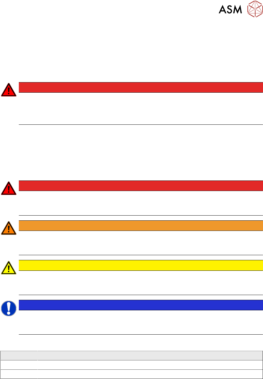
DANGER
Definition
For the purposes of this manual, this indicates that fatal or severe injuries or considerable
damage to property will occur if this hazard warning is not observed.
WARNING
Definition
For the purposes of this manual, this indicates that fatal or severe injuries or considerable
damage to equipment may occur if these warning instructions are not followed.
CAUTION
Definition
For the purposes of this manual, this indicates that minor injuries or damage to property
may occur if this caution is not observed.
NOTICE
Definition
For the purposes of this manual, this note provides information about the product or indic-
ates a part of the manual that requires particular attention.
Symbols
Example Description
Next This typeface marks controls and interface elements in the software.
► This symbol indicates actions that have to be performed by the operator.