00198608-02_SM_CP20P2_Kunde_EN.pdf - 第40页
5 Pressure control valve (PRV) 5.1 Replacing the support plate on the PRV 40 Service Manual SIPLACE SpeedStar (C&P20 P2) 01/2019 Removal Fig.48: Dismantling the support plate ► Remove the fastening screws (2) (TX20…
5 Pressure control valve (PRV)
5.1 Replacing the support plate on the PRV
Service Manual SIPLACE SpeedStar (C&P20 P2) 01/2019 39
5 Pressure control valve (PRV)
5.1 Replacing the support plate on the PRV
Parts
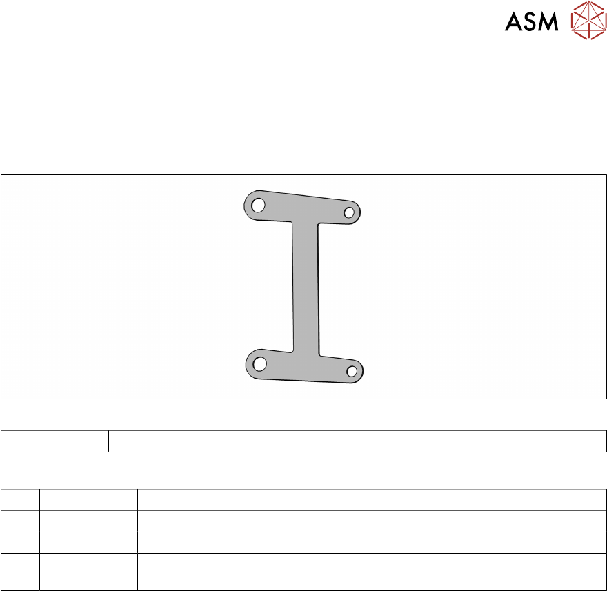
Fig.47: Support plate
03154883-xx Support plate for pneumatic valve C&P20P2
Equipment and tools
T47 00386253-xx Torque screwdriver ESD 0.4-1.0 Nm
T98 03171857-xx Torque Allen swap blade 1.5 mm TX10
T99 03171856-xx Torque Allen swap blade 1.5 mm TX20
T --- Tools for removing/fitting and calibrating the placement head, if needed
(see also the service manual for your machine)
Preparation
► Remove the head from the machine. For details about removing and fitting the placement
head, refer to the service manual for your machine.
Fit the head on the head mount [03056231‑xx].
► Make sure that the component sensor protective cap is fitted.
1.1.3 "Safety instructions for the component sensor" [}6]
5 Pressure control valve (PRV)
5.1 Replacing the support plate on the PRV
40 Service Manual SIPLACE SpeedStar (C&P20 P2) 01/2019
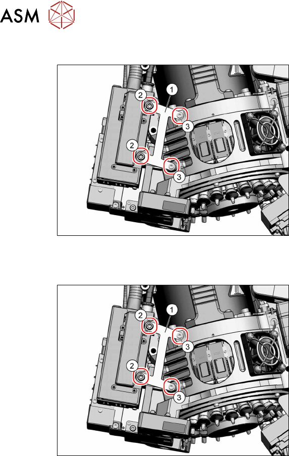
Removal
Fig.48: Dismantling the support plate
► Remove the fastening screws(2)
(TX20) and(3) (TX10) and then
remove the support plate(1).
Installation
Fig.49: Fitting the support plate
► Fasten the support plate(1) with the
screws(3) (TX10, M3x6, torque
0.6Nm) and(2) (TX20, M4x25, torque
0.9Nm).
5 Pressure control valve (PRV)
5.2 Replacing the pressure control valve (PRV)
Service Manual SIPLACE SpeedStar (C&P20 P2) 01/2019 41
5.2 Replacing the pressure control valve (PRV)
Parts
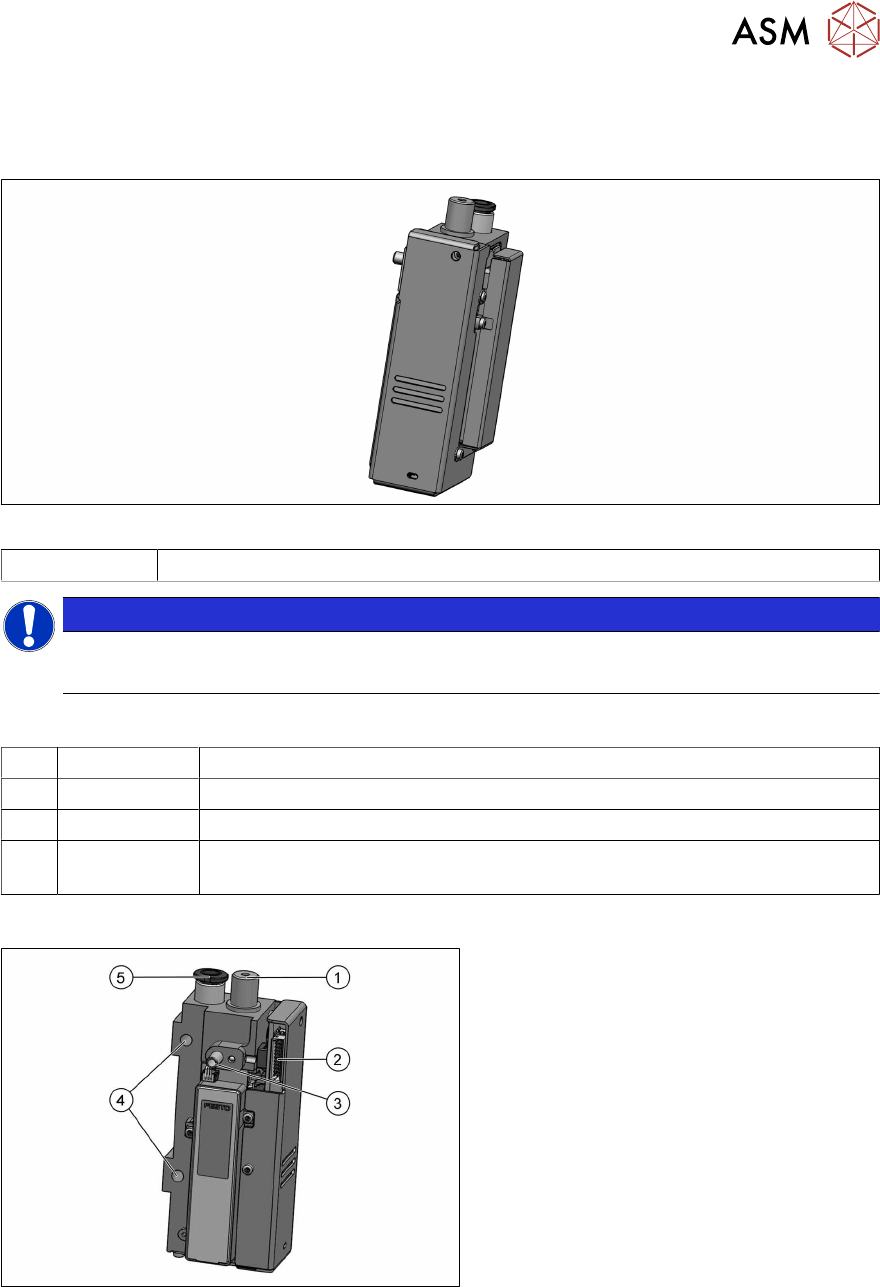
Fig.50: Pressure control valve (PRV)
03136795‑xx Pressure control valve (PRV)
NOTICE
Damaged cable
► If the cable is damaged, contact the SIPLACE service team.
Equipment and tools
T47 00386253-xx Torque screwdriver ESD 0.4-1.0 Nm
T99 03171856-xx Torque Allen swap blade 1.5 mm TX20
C08 00308458-xx Cable ties B=2.5mm, L=102mm Panduit
T --- Tools for removing/fitting and calibrating the placement head, if needed
(see also the service manual for your machine)
Overview
Fig.51: Overview of PRV
1. Exhaust air, for cooling the X linear mo-
tor
2. Energy and data supply
3. Vacuum/air blast for pickup/placement
circuit
4. Holes for the screws fastening the PRV
(TX20)
5. Compressed air connection
Preparation
► Remove the head from the machine. For details about removing and fitting the placement
head, refer to the service manual for your machine.
Fit the head on the head mount [03056231‑xx].
► Make sure that the component sensor protective cap is fitted.
1.1.3 "Safety instructions for the component sensor" [}6]