00198608-02_SM_CP20P2_Kunde_EN.pdf - 第47页
6 Aperture ring, holding circuit and silencer 6.1 Replacing the aperture ring/holding circuit/sealing disc Service Manual SIPLACE SpeedStar (C&P20 P2) 01/2019 47 Preparation ► Remove the head from the machine. For de…
6 Aperture ring, holding circuit and silencer
6.1 Replacing the aperture ring/holding circuit/sealing disc
46 Service Manual SIPLACE SpeedStar (C&P20 P2) 01/2019
Parts – compressed air operation
NOTICE
The SIPLACE C&P20P2 with compressed air mode had not been released by the time this
document was published.
► Contact the SIPLACE Service team for details.
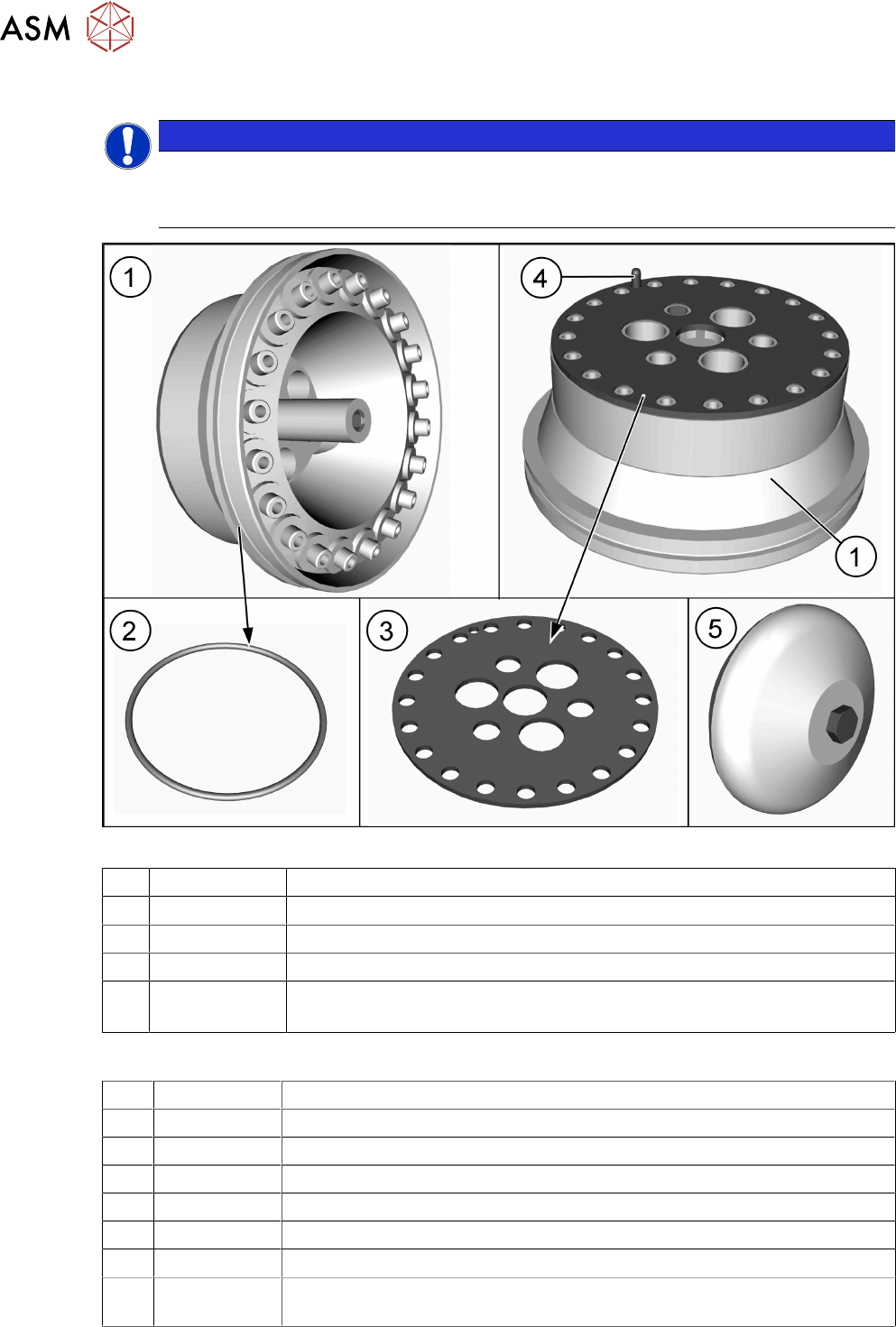
Fig.57: Holding circuit
1 03005123Sxx Holding circuit - vacuum unit
2 03046689-xx O-ring 50x1.5
3 03005120-xx Sealing disc for SIPLACE C&P20
4 --- Pins
5 03043707-xx Silencer assembly C&P20
See: 6.2 "Replacing the silencer (venturi mode only)" [}50]
Equipment and tools
T07 03078400-xx Torque Screwdriver ESD 1.0-5.0 Nm
T78 03090019-xx Torque interchangeable blades 2.5 mm, hexagonal
T98 03171857-xx Torque Allen swap blade 1.5 mm TX10
C03 03082092-xx Cleaning Wipe, KM-Wipe
C05 --- Isopropanol
C06 00352931-xx SIPLACE clean sticks
C11 03078517-xx ISOFLEX Topas 5051 50ml
T --- Tools for removing/fitting and calibrating the placement head, if needed
(see also the service manual for your machine)
6 Aperture ring, holding circuit and silencer
6.1 Replacing the aperture ring/holding circuit/sealing disc
Service Manual SIPLACE SpeedStar (C&P20 P2) 01/2019 47
Preparation
► Remove the head from the machine. For details about removing and fitting the placement
head, refer to the service manual for your machine.
Fit the head on the head mount [03056231‑xx].
► Make sure that the component sensor protective cap is fitted.
1.1.3 "Safety instructions for the component sensor" [}6]
Removal
NOTICE
Description example
The description uses the example of the aperture ring. The procedure for the holding circuit
is the same. Any relevant differences will be mentioned explicitly.
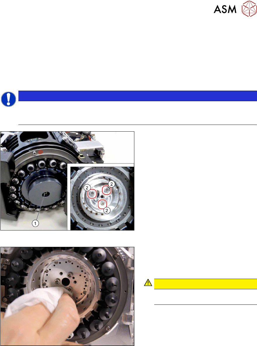
Fig.58: Dismantling the cover and aperture ring
► Remove the fastening screw(1) (TX10)
and then take off the cover.
► Remove the three screws(2) (TX10)
fastening the aperture ring.
► Carefully lever the aperture ring off the
locating pins. Make sure that the O-ring
is not damaged.
Fig.59: Cleaning
► Clean the seat of the aperture ring with
a cleaning cloth, coated with isopro-
panol.
CAUTION!
Do not use compressed air for
cleaning!
.
6 Aperture ring, holding circuit and silencer
6.1 Replacing the aperture ring/holding circuit/sealing disc
48 Service Manual SIPLACE SpeedStar (C&P20 P2) 01/2019
Installation
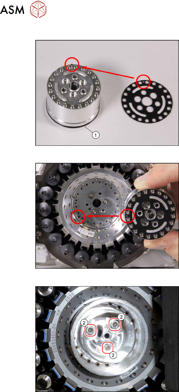
Fig.60: O‑Ring and sealing disc
► If the O-ring (1) is damaged, replace it
with a new one.
► Correctly position the sealing disc on
the aperture ring. Make sure all open-
ings are aligned. Pay attention to the
pin.
Fig.61: Inserting the aperture ring
► Position the aperture ring and sealing
disc correctly in the star carrier. Pay at-
tention to the pin.
Fig.62: Fasten the aperture ring
► Vacuum pump operation with aper-
ture ring only: Fix the aperture ring
with the three fastening screws (1)
(TX10, M3x10, torque 1.3 Nm).
► Venturi operation with holding cir-
cuit only: Fix the holding circuit into
place with the three fastening screws.
(TX10, M3x10, torque 0.25Nm).