00198608-02_SM_CP20P2_Kunde_EN.pdf - 第50页
6 Aperture ring, holding circuit and silencer 6.2 Replacing the silencer (venturi mode only) 50 Service Manual SIPLACE SpeedStar (C&P20 P2) 01/2019 6.2 Replacing the silencer (venturi mode only) Parts Fig.65: Silenc…
6 Aperture ring, holding circuit and silencer
6.1 Replacing the aperture ring/holding circuit/sealing disc
Service Manual SIPLACE SpeedStar (C&P20 P2) 01/2019 49
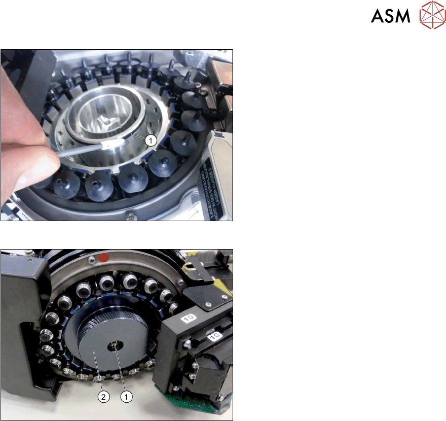
Fig.63: Greasing the O-ring
► Grease the O-ring. To do this, use a
cleaning stick coated with "Isoflex To-
pas 5051 50ml (green)".
Fig.64: Fitting the cover
► Vacuum pump operation:
Fit the cover (2) with a screw(1) (TX10,
M4x14, torque 1.3Nm).
► Venturi operation only:
Fit the silencer. Tighten the screw
fastening the silencer by hand.
6 Aperture ring, holding circuit and silencer
6.2 Replacing the silencer (venturi mode only)
50 Service Manual SIPLACE SpeedStar (C&P20 P2) 01/2019
6.2 Replacing the silencer (venturi mode only)
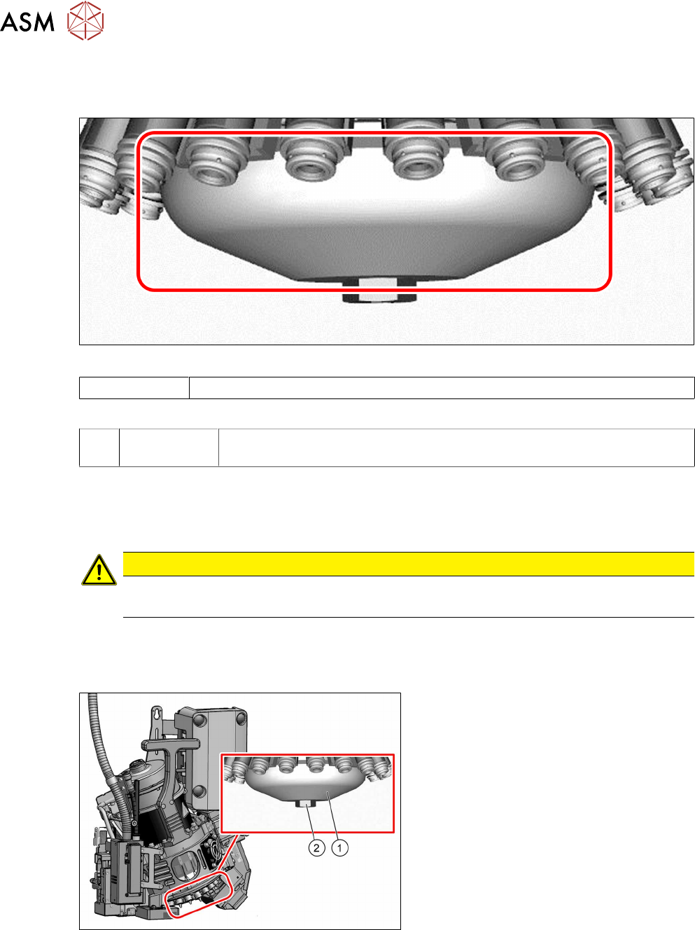
Parts
Fig.65: Silencer
03043707-xx Silencer
Equipment and tools
T --- Tools for removing/fitting and calibrating the placement head, if needed
(see also the service manual for your machine)
Preparation
► Remove the head from the machine. For details about removing and fitting the placement
head, refer to the service manual for your machine.
Fit the head on the head mount [03056231‑xx].
CAUTION
Camera
► Make sure that you do not damage or contaminate the camera lens system.
► Make sure that the component sensor protective cap is fitted.
1.1.3 "Safety instructions for the component sensor" [}6]
Removal
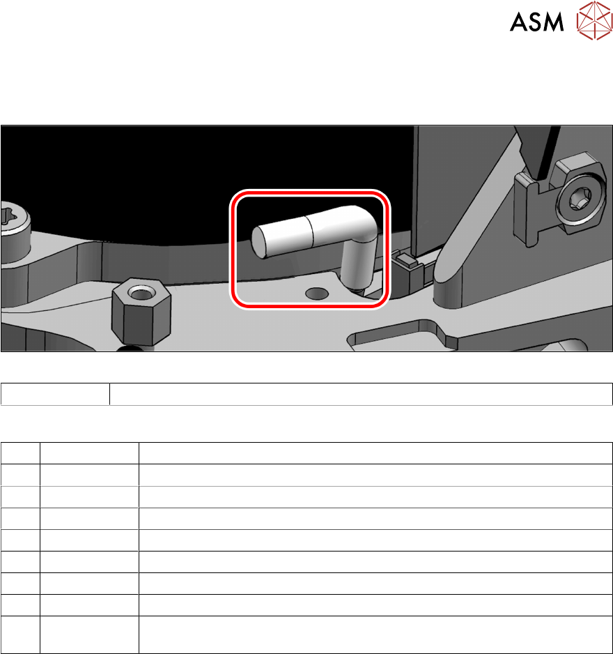
Fig.66: Silencer
► Remove the screw (2) fastening the si-
lencer (1).
► Carefully lever out the silencer.
Installation
► Follow the removal instructions in reverse order for installation. Also observe the following
instructions:
– Carefully press the new silencer down, onto the holding circuit.
– Carefully hand-tighten the screw fastening the silencer.
6 Aperture ring, holding circuit and silencer
6.3 Replacing the holding circuit hose
Service Manual SIPLACE SpeedStar (C&P20 P2) 01/2019 51
6.3 Replacing the holding circuit hose
Parts
Fig.67: Holding circuit hose
03154858S01 Holding circuit hose CP20 P2 S 2
Equipment and tools
T07 03078400-xx Torque Screwdriver ESD 1.0-5.0 Nm
T19 00318673-xx Wire cutter electronic size 110
T44 00386132-xx Torque screwdriver ESD 0.1-0,6 Nm
T47 00386253-xx Torque screwdriver ESD 0.4-1.0 Nm
T78 03090019-xx Torque interchangeable blades 2.5 mm, hexagonal
T98 03171857-xx Torque Allen swap blade 1.5 mm TX10
T 00381443‑xx Pipe/hose cutters Festo ZRS 7658
C08 00308458-xx Cable ties B=2.5mm, L=102mm Panduit
T --- Tools for removing/fitting and calibrating the placement head, if needed
(see also the service manual for your machine)
Preparation
► Remove the head from the machine. For details about removing and fitting the placement
head, refer to the service manual for your machine.
Fit the head on the head mount [03056231‑xx].
► Make sure that the component sensor protective cap is fitted.
1.1.3 "Safety instructions for the component sensor" [}6]