00198608-02_SM_CP20P2_Kunde_EN.pdf - 第52页
6 Aperture ring, holding circuit and silencer 6.3 Replacing the holding circuit hose 52 Service Manual SIPLACE SpeedStar (C&P20 P2) 01/2019 Removal ► Dismantle the component camera. 3.1 "Replacing the Component …
6 Aperture ring, holding circuit and silencer
6.3 Replacing the holding circuit hose
Service Manual SIPLACE SpeedStar (C&P20 P2) 01/2019 51
6.3 Replacing the holding circuit hose
Parts
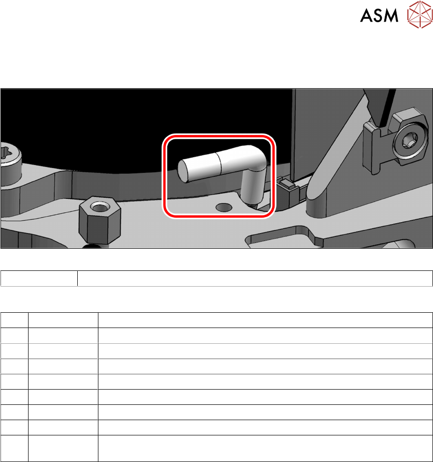
Fig.67: Holding circuit hose
03154858S01 Holding circuit hose CP20 P2 S 2
Equipment and tools
T07 03078400-xx Torque Screwdriver ESD 1.0-5.0 Nm
T19 00318673-xx Wire cutter electronic size 110
T44 00386132-xx Torque screwdriver ESD 0.1-0,6 Nm
T47 00386253-xx Torque screwdriver ESD 0.4-1.0 Nm
T78 03090019-xx Torque interchangeable blades 2.5 mm, hexagonal
T98 03171857-xx Torque Allen swap blade 1.5 mm TX10
T 00381443‑xx Pipe/hose cutters Festo ZRS 7658
C08 00308458-xx Cable ties B=2.5mm, L=102mm Panduit
T --- Tools for removing/fitting and calibrating the placement head, if needed
(see also the service manual for your machine)
Preparation
► Remove the head from the machine. For details about removing and fitting the placement
head, refer to the service manual for your machine.
Fit the head on the head mount [03056231‑xx].
► Make sure that the component sensor protective cap is fitted.
1.1.3 "Safety instructions for the component sensor" [}6]
6 Aperture ring, holding circuit and silencer
6.3 Replacing the holding circuit hose
52 Service Manual SIPLACE SpeedStar (C&P20 P2) 01/2019
Removal
► Dismantle the component camera.
3.1 "Replacing the Component Camera" [}13]
► Dismantle the holding circuit board
9.3 "Replacing the holding circuit board" [}71]
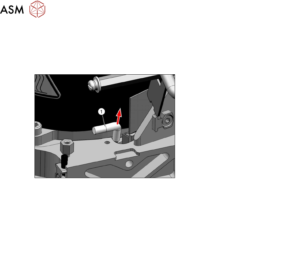
Fig.68: Holding circuit hose
► Pull the holding circuit hose(1) up and
off.
Installation
► Cut the new hose to a length of 22 +/- 1mm.
► Follow the removal instructions in reverse order for further installation.
Also observe the installation instructions in the following sections:
9.3 "Replacing the holding circuit board" [}71]
3.1 "Replacing the Component Camera" [}13]
► Observe in particular the torques specified!
► Replace any cable ties which you have removed.
6 Aperture ring, holding circuit and silencer
6.4 Replacing the placement circuit hose
Service Manual SIPLACE SpeedStar (C&P20 P2) 01/2019 53
6.4 Replacing the placement circuit hose
Parts
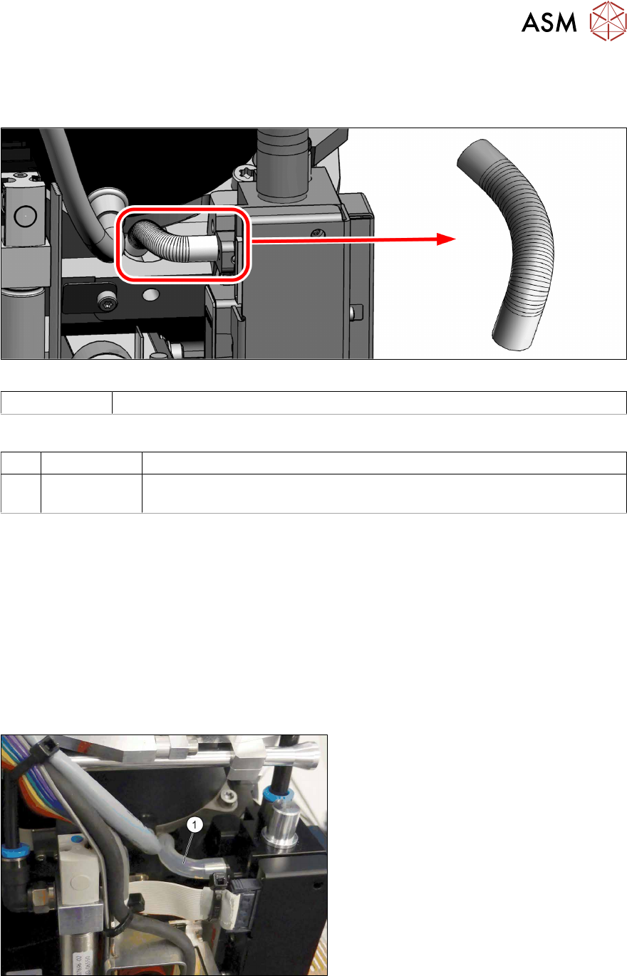
Fig.69: Placement circuit hose (on the back of the PRV)
03154926Sxx Placement circuit hose SIPLACE C&P20 P2 S 2
Equipment and tools
T 00381443‑xx Pipe/hose cutters Festo ZRS 7658
T --- Tools for removing/fitting and calibrating the placement head, if needed
(see also the service manual for your machine)
Preparation
► Remove the head from the machine. For details about removing and fitting the placement
head, refer to the service manual for your machine.
Fit the head on the head mount [03056231‑xx].
► Make sure that the component sensor protective cap is fitted.
1.1.3 "Safety instructions for the component sensor" [}6]
Removal
► There is no need to remove the pressure control valve (PRV) but it might be helpful to im-
prove the accessibility.
5.2 "Replacing the pressure control valve (PRV)" [}41]
Fig.70: Hose for placement circuit
► Pull off the hose(1) from the pressure
control valve and the head housing.