00198608-02_SM_CP20P2_Kunde_EN.pdf - 第58页
7 Screwed joint 7.2 Replacing the screwed joint 58 Service Manual SIPLACE SpeedStar (C&P20 P2) 01/2019 Fig.77: Screwed joint ► Remove the four screws (TX6) fasten- ing the screwed joint (1) . ► Pull the screwed joi…
7 Screwed joint
7.2 Replacing the screwed joint
Service Manual SIPLACE SpeedStar (C&P20 P2) 01/2019 57
7.2 Replacing the screwed joint
Parts
Fig.75: Screwed joint assembly
03134264-xx Screwed joint assembly SIPLACE C&P20P2
Equipment and tools
T44 00386132-xx Torque screwdriver ESD 0.1-0,6 Nm
T96 03171858-xx Torque Allen swap blade 1.5 mm TX6
C 00310259-xx Lubricant Unisilikon L 250 L 60gr tube
T --- Tools for removing/fitting and calibrating the placement head, if needed
(see also the service manual for your machine)
Preparation
► Remove the head from the machine. For details about removing and fitting the placement
head, refer to the service manual for your machine.
Fit the head on the head mount [03056231‑xx].
► Make sure that the component sensor protective cap is fitted.
1.1.3 "Safety instructions for the component sensor" [}6]
Removal
► Dismantling the cover cap
7.1 "Replacing the cover cap and grommet" [}55]
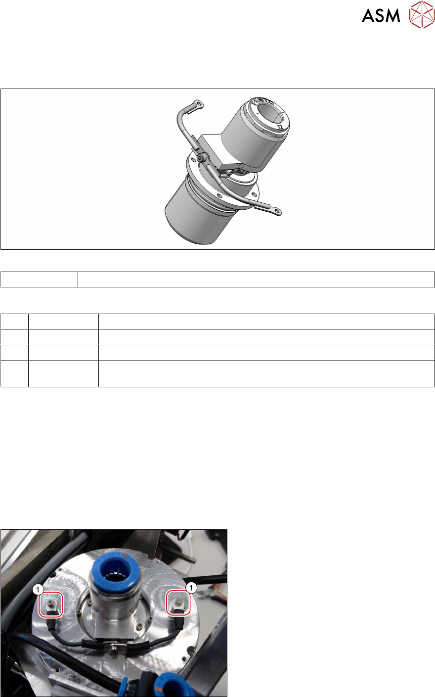
Fig.76: Ground connections
► Remove the two screws(1) (TX6)
fastening the ground connections.
Pay attention to the toothed disks.
7 Screwed joint
7.2 Replacing the screwed joint
58 Service Manual SIPLACE SpeedStar (C&P20 P2) 01/2019
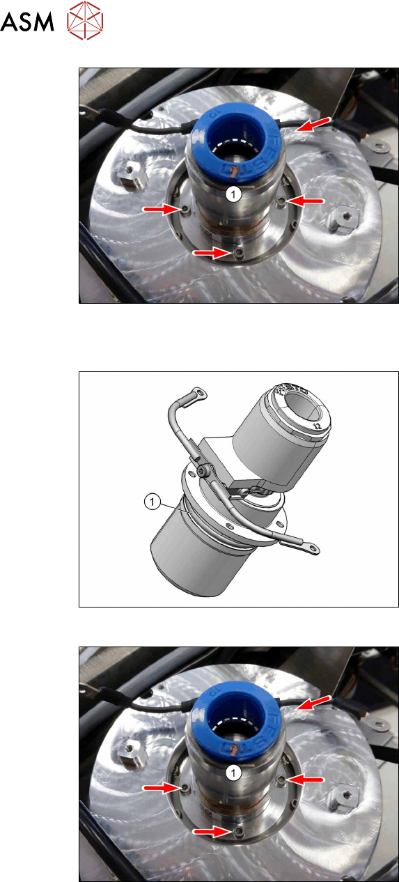
Fig.77: Screwed joint
► Remove the four screws (TX6) fasten-
ing the screwed joint(1).
► Pull the screwed joint up and out of the
head. You may need to apply some ef-
fort.
Installation
Fig.78: O-ring on the screwed joint
► Grease the rubber ring [03134226‑xx]
on the screwed joint slightly with unisi-
likon.
Fig.79: Screwed joint
► Insert the screwed joint(1) into the
head. Try and hit the screwed holes
well and first time, as subsequent
screwing in is only possible with great
effort.
► Fasten the screwed joint with the four
screws (TX6, M2x6, torque 0.56Nm).
7 Screwed joint
7.2 Replacing the screwed joint
Service Manual SIPLACE SpeedStar (C&P20 P2) 01/2019 59
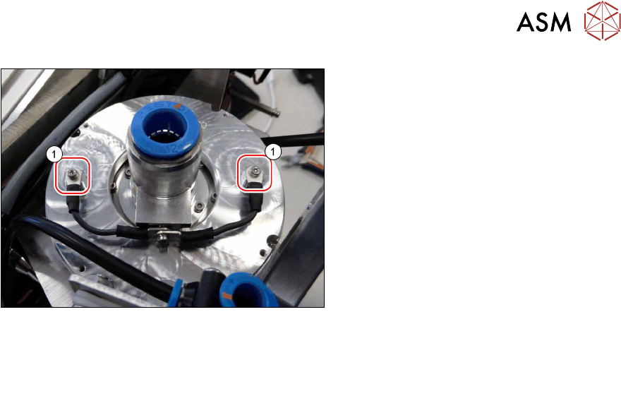
Fig.80: Ground connections
► Fasten the two ground connections(1)
with one screw each (TX6. M2x4,
torque 0.35Nm). Place a toothed disk
below and one above each ground con-
nection.
► Follow the removal instructions in reverse order for further installation.
Also observe the installation instructions in the following section:
7.1 "Replacing the cover cap and grommet" [}55]
► Observe in particular the torques specified!