00198608-02_SM_CP20P2_Kunde_EN.pdf - 第64页
8 Return unit 8.1 Replacing the return unit, cylinder, holder and driver lever 64 Service Manual SIPLACE SpeedStar (C&P20 P2) 01/2019 Fitting the return cylinder holder Fig.87: Driver lever - fastening screw ► Fit t…
8 Return unit
8.1 Replacing the return unit, cylinder, holder and driver lever
Service Manual SIPLACE SpeedStar (C&P20 P2) 01/2019 63
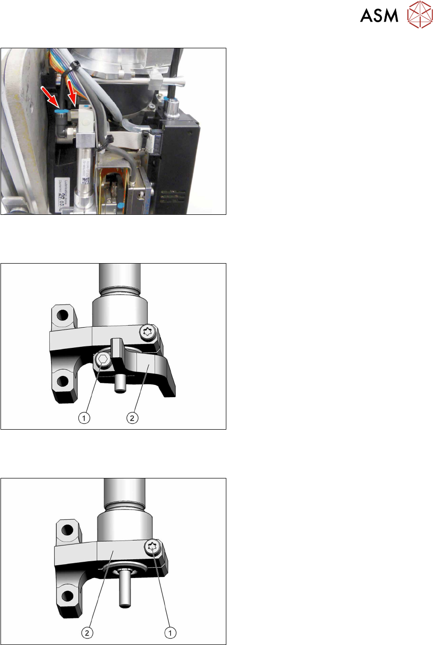
Fig.84: Electrical and pneumatic connections
► Unplug all electrical and pneumatic
connections. If necessary, mark their
positions to make clear assignment
easier later on.
► If you are replacing the whole return
unit assembly, continue with the install-
ation of the return unit.
Removing the driver lever
Fig.85: Driver lever - fastening screw
► Loosen the screw(1) (Allen2) fasten-
ing the driver lever(2).
► Pull the driver lever down and off.
► If you are only replacing the driver
lever, continue with installation of the
driver lever.
Removing the return cylinder holder
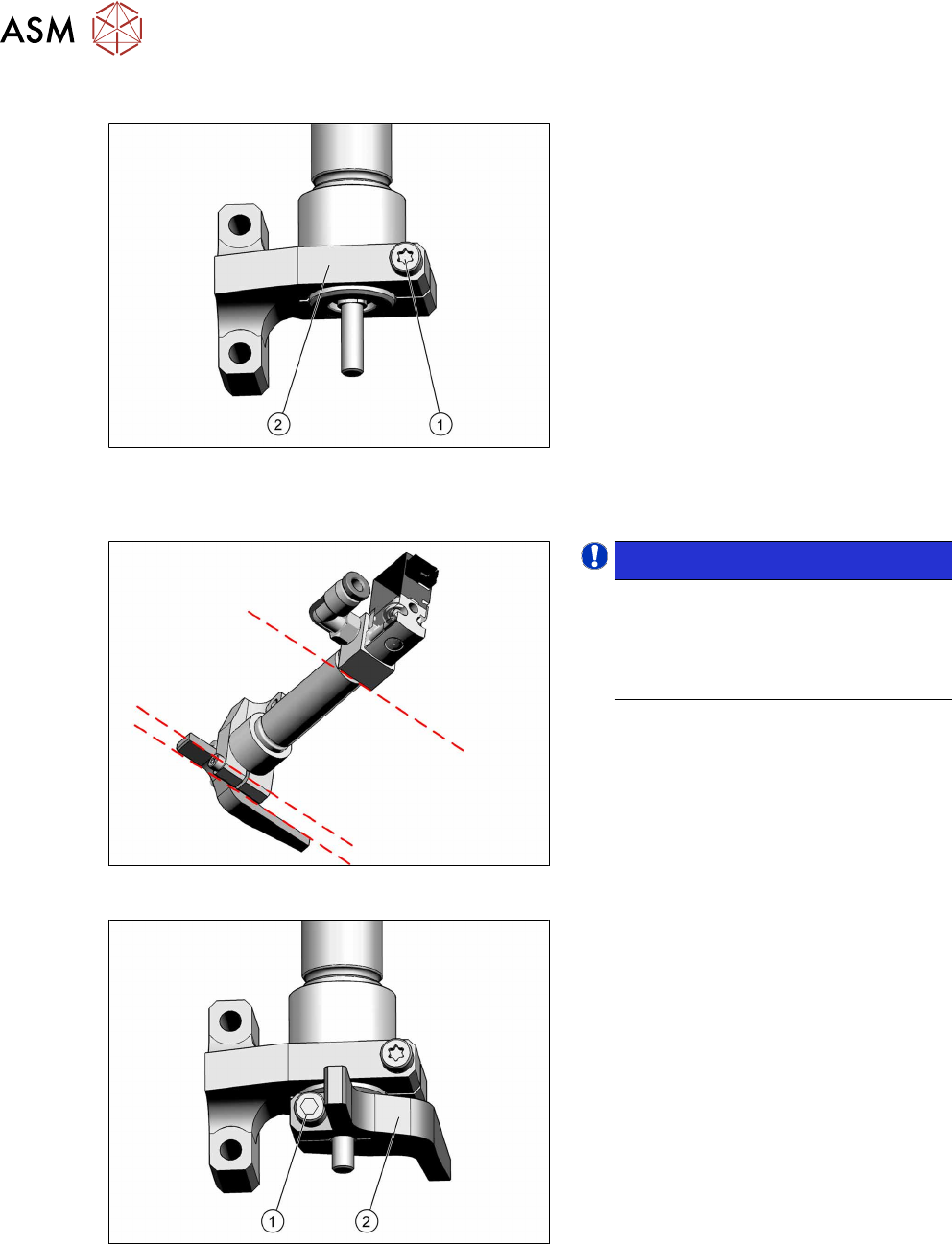
Fig.86: Driver lever - fastening screw
► Loosen the screw(1) (TX8) fastening
the return cylinder holder(2).
► Pull the return cylinder holder down
and off.
8 Return unit
8.1 Replacing the return unit, cylinder, holder and driver lever
64 Service Manual SIPLACE SpeedStar (C&P20 P2) 01/2019
Fitting the return cylinder holder
Fig.87: Driver lever - fastening screw
► Fit the return cylinder holder(2) onto
the return cylinder.
There should be no gap between the
pneumatic cylinder and the holder.
Tighten the screw(1) (TX8, M2.5x14)
with a torque of 0.65Nm.
Fitting the driver lever
Fig.88: Parallelism
NOTICE!
Pay attention to parallelism
When assembling the return unit, pay
attention to the parallelism of the re-
turn cylinder, return cylinder holder
and the driver lever.
.
Fig.89: Driver lever - fastening screw
► Fit the driver lever(2) onto the return
unit.
To do this, attach the driver lever fully
onto the pin of the return unit.
Tighten the screw(1) (Allen2,
M2.5x10) with a torque of 1.15Nm.
8 Return unit
8.1 Replacing the return unit, cylinder, holder and driver lever
Service Manual SIPLACE SpeedStar (C&P20 P2) 01/2019 65
Fitting the return unit
Fig.90: Dismantling the return cylinder
► Restore all electrical and pneumatic
connections between the return unit
and the head.
► Fit the return unit with the holder as far
as the end stop.
Tighten the two screws(1) (TX10,
M3x14) fastening the return unit with a
torque of 1.3Nm.
► Replace any cable ties which you have removed.
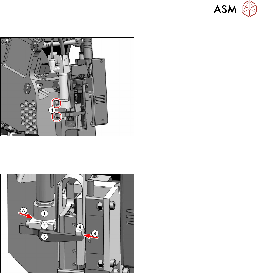
Checks
Fig.91: Inspection checks
► Perform the following checks:
– Make sure that there is no gap (A)
between the pneumatic cylinder (1)
and the holder(2).
– The driver lever must lie against the
Z axis.
– Check that the star can be revolved.
This should not scrape.
– Check the distance(B) between the
driver lever(3) and the rotor(4) of
the Z motor with a feeler gauge. The
distance should be approx. 0.5 mm
when the Z axis is pushed upwards.
► If there are any problems, go through
the aforementioned inspection steps
again.