00198608-02_SM_CP20P2_Kunde_EN.pdf - 第67页
9 Boards 9.1 Replacing the intermediate distributor board (ID) Service Manual SIPLACE SpeedStar (C&P20 P2) 01/2019 67 9 Boards See also 2 3.1.1 "Board: Vision LED controller VLC48" [ } 16] 9.1 Replacing th…

8 Return unit
8.1 Replacing the return unit, cylinder, holder and driver lever
66 Service Manual SIPLACE SpeedStar (C&P20 P2) 01/2019
9 Boards
9.1 Replacing the intermediate distributor board (ID)
Service Manual SIPLACE SpeedStar (C&P20 P2) 01/2019 67
9 Boards
See also
2 3.1.1 "Board: Vision LED controller VLC48" [}16]
9.1 Replacing the intermediate distributor board (ID)
Parts
03134908-xx Intermediate distributor board for SIPLACE C&P20P2
Equipment and tools
T19 00318673-xx Wire cutter electronic size 110
T33 00096290-xx Spanner set 15 pcs
T44 00386132-xx Torque screwdriver ESD 0.1-0,6 Nm
T96 03171858-xx Torque Allen swap blade 1.5 mm TX6
T 00376503-xx Set of Torx offset screwdrivers with spherical heads
C08 00308458-xx Cable ties B=2.5mm, L=102mm Panduit
C 00351416‑xx Loctite 222
T --- Tools for removing/fitting and calibrating the placement head, if needed
(see also the service manual for your machine)
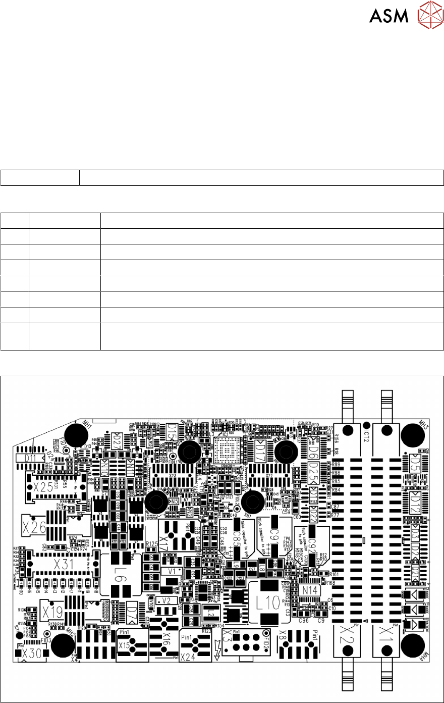
Overview
Fig.92: Overview of intermediate distributor SIPLACE C&P20 P2
9 Boards
9.1 Replacing the intermediate distributor board (ID)
68 Service Manual SIPLACE SpeedStar (C&P20 P2) 01/2019
Preparation
► Remove the head from the machine. For details about removing and fitting the placement
head, refer to the service manual for your machine.
Fit the head on the head mount [03056231‑xx].
► Make sure that the component sensor protective cap is fitted.
1.1.3 "Safety instructions for the component sensor" [}6]
Removal
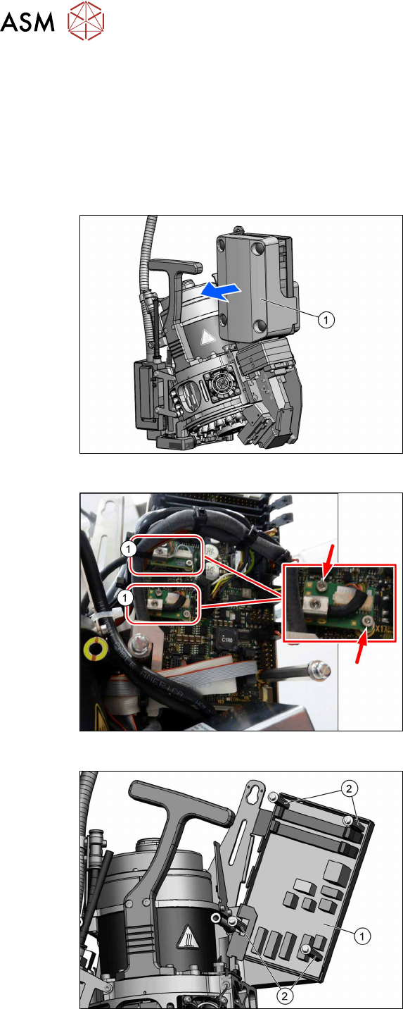
Fig.93: Pulling the cover off
► Pull the cover(1) off the intermediate
distributor.
The cover is fixed by four press studs
on the stay bolts.
Fig.94: Circuit board connector
► Unplug all electrical connections to the
intermediate distributor. Mark their pos-
itions to make clear assignment easier
later on.
Take particular care not to confuse the
two board connectors(1).
The board connectors are each se-
cured with two screws (TX6).
Fig.95: Bolts
► Remove the four fastening bolts(2)
(SW3) and then remove the intermedi-
ate distributor(1).