00198608-02_SM_CP20P2_Kunde_EN.pdf - 第69页
9 Boards 9.1 Replacing the intermediate distributor board (ID) Service Manual SIPLACE SpeedStar (C&P20 P2) 01/2019 69 Installation Fig.96: Fitting the board ► Fasten the board (1) with the four bolts (2) . Secure …
9 Boards
9.1 Replacing the intermediate distributor board (ID)
68 Service Manual SIPLACE SpeedStar (C&P20 P2) 01/2019
Preparation
► Remove the head from the machine. For details about removing and fitting the placement
head, refer to the service manual for your machine.
Fit the head on the head mount [03056231‑xx].
► Make sure that the component sensor protective cap is fitted.
1.1.3 "Safety instructions for the component sensor" [}6]
Removal
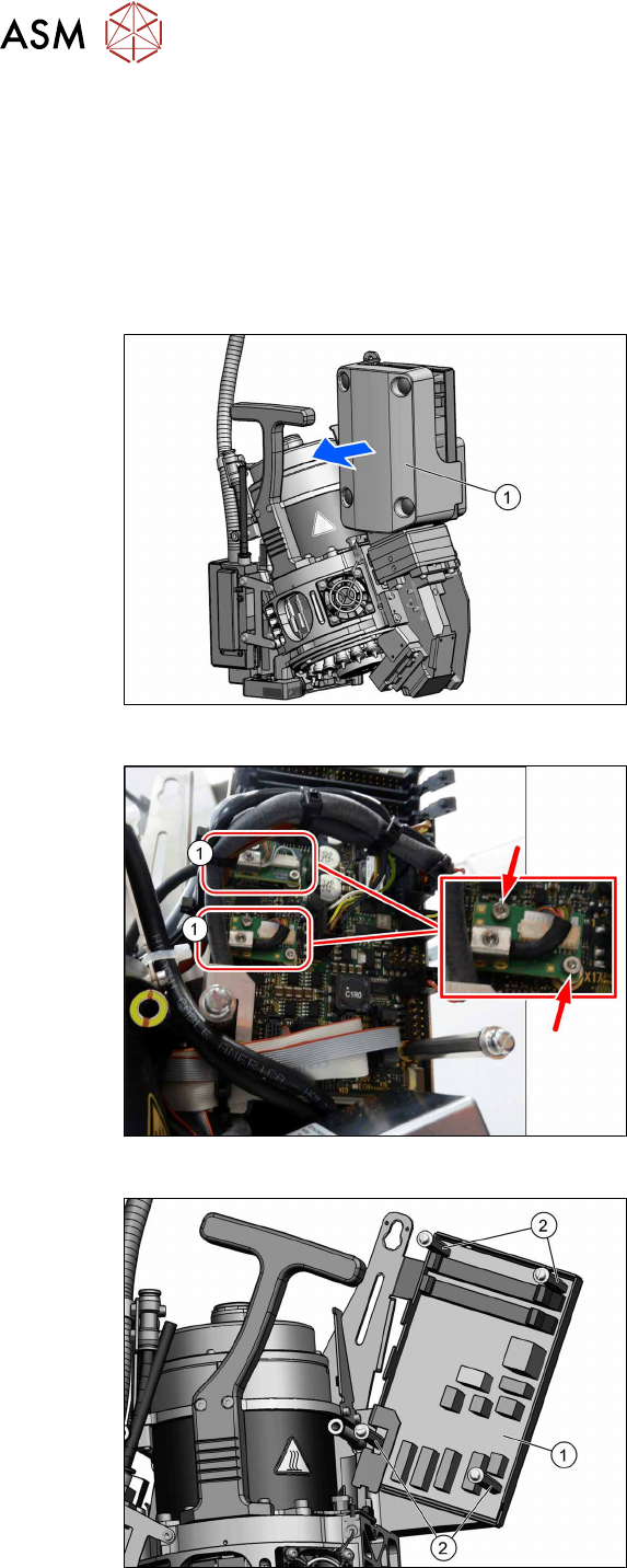
Fig.93: Pulling the cover off
► Pull the cover(1) off the intermediate
distributor.
The cover is fixed by four press studs
on the stay bolts.
Fig.94: Circuit board connector
► Unplug all electrical connections to the
intermediate distributor. Mark their pos-
itions to make clear assignment easier
later on.
Take particular care not to confuse the
two board connectors(1).
The board connectors are each se-
cured with two screws (TX6).
Fig.95: Bolts
► Remove the four fastening bolts(2)
(SW3) and then remove the intermedi-
ate distributor(1).
9 Boards
9.1 Replacing the intermediate distributor board (ID)
Service Manual SIPLACE SpeedStar (C&P20 P2) 01/2019 69
Installation
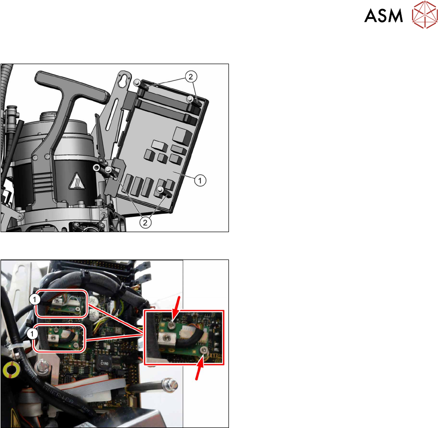
Fig.96: Fitting the board
► Fasten the board(1) with the four
bolts(2). Secure the bolts with Loctite
222.
Fig.97: Circuit board connector
► Restore all electrical connections to the
intermediate distributor.
Fasten the board connectors(1) with
two screws each (TX6, torque
0.2Nm).
► Follow the removal instructions in reverse order for further installation.
► Transfer the machine data for the station to the EPROM of the intermediate distributor.
9 Boards
9.2 Intermediate distributor board for SIPLACE C&P20P2
70 Service Manual SIPLACE SpeedStar (C&P20 P2) 01/2019
9.2 Intermediate distributor board for SIPLACE C&P20P2
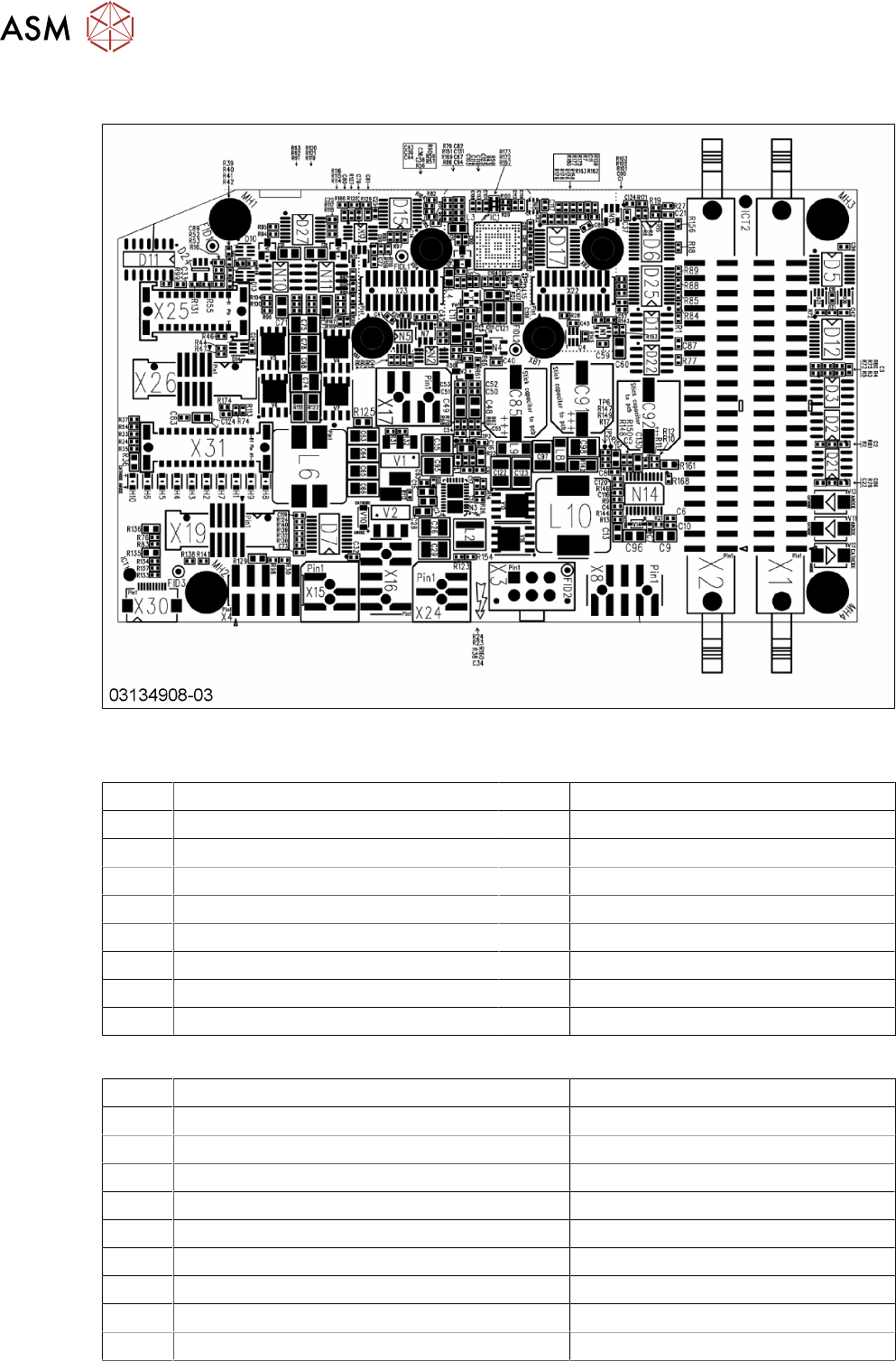
Fig.98: Intermediate distributor board for SIPLACE C&P20P2 [03134908-03]
Connector [03134908‑03]
X1,X2 Flat ribbon cable to the head adapter X3 Power supply for star motor
X4 Test connector X8 Power supply for Z axis
X15 Valve for return unit X16 CAN bus
X16b CAN bus X17 Z axis light barrier down
X19 Holding circuit board X20 Power supply for ED distributor
X21 Diagnosis connector X22 Incremental encoder for star and Z
X23 Incremental Z axis X24 Fan
X25 Digital pressure control valve X26 CO sensor
X30 Diagnostic FPGA X31 KED stator ring
LEDs [03134908‑03]
H1 Return unit Amber
H2 3.3 V Green
H3 5 V Green
H4 15 V Green
H5 24 V Green
H6 30V Green
H7 5 V pressure control valve Amber
H8 Fan FAN Amber
H9 Fan error ERR Red
H10 EON error 24 V DP (ground PWRGD_Dp) Green