00198608-02_SM_CP20P2_Kunde_EN.pdf - 第74页
9 Boards 9.3 Replacing the holding circuit board 74 Service Manual SIPLACE SpeedStar (C&P20 P2) 01/2019
9 Boards
9.3 Replacing the holding circuit board
Service Manual SIPLACE SpeedStar (C&P20 P2) 01/2019 73
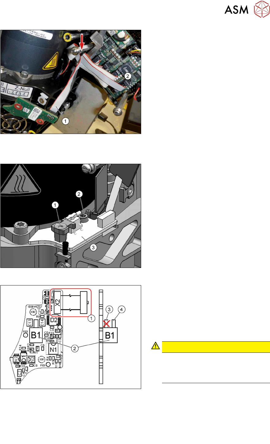
Fig.103: Unplugging the cable
► Remove the cable ties and unthread
the cable(1) as far as the circuit board
for the intermediate distributor(2).
Installation
Fig.104: Fastening the board
► Fit the holding circuit board into place
with two screws. Pay attention to the
different sizes of screws and to the
torques.
1. Front screw: M3x5 (TX10)
Torque: 0.6Nm
2. Back screw: M3x8 (TX10)
Torque: 0.2Nm
Fig.105: Board for holding circuit assembly SIPLACE
C&P20 P2
► Reconnect to the electricity supply.
(1)Connector X2 and cable to the inter-
mediate distributor
► Connect the hose to the pressure
sensor(2) (holding circuit/aperture
ring).
Use the top hose connection(4)for this.
CAUTION!
Do NOT use the bottom hose con-
nection(3) directly above the circuit
board. This connection remains
free.
.
► Follow the removal instructions in reverse order for further installation.
Also observe the installation instructions in the following section:
3.1 "Replacing the Component Camera" [}13]
► Observe in particular the torques specified!
► Replace any cable ties which you have removed.

9 Boards
9.3 Replacing the holding circuit board
74 Service Manual SIPLACE SpeedStar (C&P20 P2) 01/2019
10 Miscellaneous (fan, retaining elements)
10.1 Replacing the fan
Service Manual SIPLACE SpeedStar (C&P20 P2) 01/2019 75
10 Miscellaneous (fan, retaining elements)
10.1 Replacing the fan
Parts
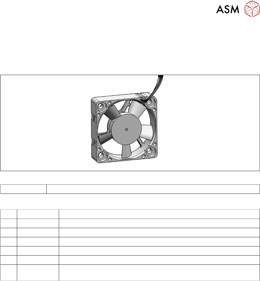
Fig.106: Fan
03104369-xx Fan assembly SIPLACE C&P20 P/P2
Equipment and tools
T07 03078400-xx Torque Screwdriver ESD 1.0-5.0 Nm
T19 00318673-xx Wire cutter electronic size 110
T44 00386132-xx Torque screwdriver ESD 0.1-0,6 Nm
T77 00386136-xx Torque interchangeable blades 2 mm, hexagonal
T98 03171857-xx Torque Allen swap blade 1.5 mm TX10
C08 00308458-xx Cable ties B=2.5mm, L=102mm Panduit
T --- Tools for removing/fitting and calibrating the placement head, if needed
(see also the service manual for your machine)
Preparation
► Remove the head from the machine. For details about removing and fitting the placement
head, refer to the service manual for your machine.
Fit the head on the head mount [03056231‑xx].
► Make sure that the component sensor protective cap is fitted.
1.1.3 "Safety instructions for the component sensor" [}6]