00198608-02_SM_CP20P2_Kunde_EN.pdf - 第80页
10 Miscellaneous (fan, retaining elements) 10.2 Replacing the retaining element mount and mount 80 Service Manual SIPLACE SpeedStar (C&P20 P2) 01/2019 Fig.115: Top left mount Only for top left mount: ► Fasten the tw…
10 Miscellaneous (fan, retaining elements)
10.2 Replacing the retaining element mount and mount
Service Manual SIPLACE SpeedStar (C&P20 P2) 01/2019 79
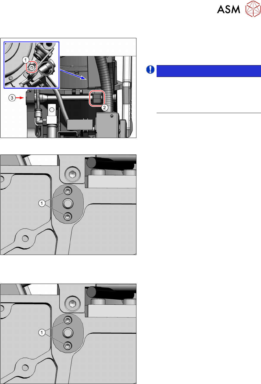
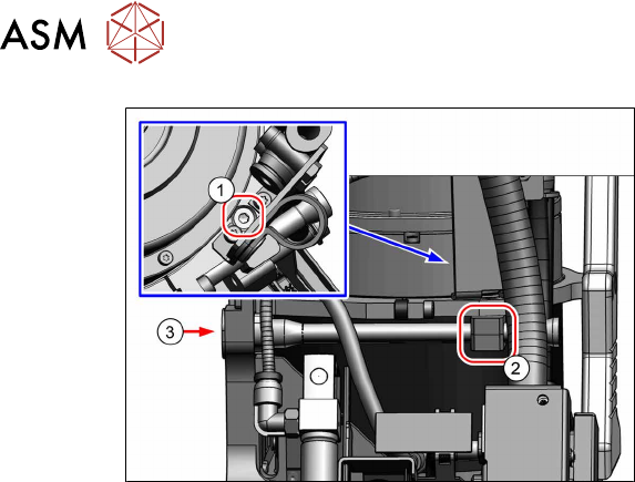
Removal
Fig.112: Top left mount
Only for top left mount:
► Remove the fastening screw(1) (TX8)
and then remove the bottom mount(2).
NOTICE!
The top part of the mount is still
clamped into place by the retaining
element. This can be taken off as soon
as the retaining element is loosened
from behind(3).
.
Fig.113: Screws fastening the retaining element
► Remove the two screws(1) (Allen1.5)
fastening the retaining element to the
back of the head.
The retaining element can now be
taken off the front of the head.
Installation
Fig.114: Screws fastening the retaining element
► Fasten the retaining element with two
screws(1) (Allen1.5, M1.6x6, torque
0.15Nm).
For top left retaining element only:
Fit the top holder at the same time.
10 Miscellaneous (fan, retaining elements)
10.2 Replacing the retaining element mount and mount
80 Service Manual SIPLACE SpeedStar (C&P20 P2) 01/2019
Fig.115: Top left mount
Only for top left mount:
► Fasten the two holders(2) with a
screw(1) (TX8, M3x16, torque
0.6Nm).

11 Software functions
11.1 Calibration
Service Manual SIPLACE SpeedStar (C&P20 P2) 01/2019 81
11 Software functions
11.1 Calibration
Overview
With the calibration of the component camera the following values are determined:
the relationship of "camera pixel size to resolution of machine measuring system (X,Y)", the "cam-
era center point in X and Y direction" and the "torsion angle of the CCD sensor in the camera".
After that, the head offset and the segment offsets for the top and bottom are determined.
●
Head offset: the head offset is the distance between the PCB camera and the nozzle (seg-
ment1). The target is a fixed value (X=0 and Y=‑105mm) to which an offset value (from the
head calibration) is added.
●
Segment offset top: the top segment offset involves turning the calibration tool in the compo-
nent camera in 0°, 90°, 180° and 270°. The value determined is that of the rotating center of
the nozzle tip in relation to the component camera center in the X and Y direction.
●
Segment offset bottom: the bottom segment offset involves recording and measuring the
calibration tool in the 0°, 90°, 180° and 270° positions. The value determined is that of the ro-
tating center point of the nozzle tip when the Z axis is extended in relation to the PCB camera.
Segment1 forms the reference (X=0,Y=0) to the other segments.
11.1.1 Calibration procedure
► Machine zero point
► Board camera
– Camera coefficient (illustration scale in nm/pixel)
– Calibration of PCB camera center point
– Calibration of PCB camera rotation to machine coordinate system
► Calibration tool position (optional)
► Travel distance X/Y axis (optional)
– Calibration of min/max gantry travel distances
► Placement head
– Pressure control valve (SIPLACE C&P20P2)
– Camera coefficient (unit nm/pixel), angle
– Head offset (offset PCB camera to component camera)
– Segment offset II (bottom)
– Segment offset I (top)
► Nozzle changers
– Calibration of pickup position for all magazines
– Calibration of pickup height
– Calibration of reject position