00198608-02_SM_CP20P2_Kunde_EN.pdf - 第82页
11 Software functions 11.1 Calibration 82 Service Manual SIPLACE SpeedStar (C&P20 P2) 01/2019 11.1.2 Calibrating the heads and cameras (SW7x) Fig.116: Select operator level ► Click on the button, to open the Configu…

11 Software functions
11.1 Calibration
Service Manual SIPLACE SpeedStar (C&P20 P2) 01/2019 81
11 Software functions
11.1 Calibration
Overview
With the calibration of the component camera the following values are determined:
the relationship of "camera pixel size to resolution of machine measuring system (X,Y)", the "cam-
era center point in X and Y direction" and the "torsion angle of the CCD sensor in the camera".
After that, the head offset and the segment offsets for the top and bottom are determined.
●
Head offset: the head offset is the distance between the PCB camera and the nozzle (seg-
ment1). The target is a fixed value (X=0 and Y=‑105mm) to which an offset value (from the
head calibration) is added.
●
Segment offset top: the top segment offset involves turning the calibration tool in the compo-
nent camera in 0°, 90°, 180° and 270°. The value determined is that of the rotating center of
the nozzle tip in relation to the component camera center in the X and Y direction.
●
Segment offset bottom: the bottom segment offset involves recording and measuring the
calibration tool in the 0°, 90°, 180° and 270° positions. The value determined is that of the ro-
tating center point of the nozzle tip when the Z axis is extended in relation to the PCB camera.
Segment1 forms the reference (X=0,Y=0) to the other segments.
11.1.1 Calibration procedure
► Machine zero point
► Board camera
– Camera coefficient (illustration scale in nm/pixel)
– Calibration of PCB camera center point
– Calibration of PCB camera rotation to machine coordinate system
► Calibration tool position (optional)
► Travel distance X/Y axis (optional)
– Calibration of min/max gantry travel distances
► Placement head
– Pressure control valve (SIPLACE C&P20P2)
– Camera coefficient (unit nm/pixel), angle
– Head offset (offset PCB camera to component camera)
– Segment offset II (bottom)
– Segment offset I (top)
► Nozzle changers
– Calibration of pickup position for all magazines
– Calibration of pickup height
– Calibration of reject position
11 Software functions
11.1 Calibration
82 Service Manual SIPLACE SpeedStar (C&P20 P2) 01/2019
11.1.2 Calibrating the heads and cameras (SW7x)
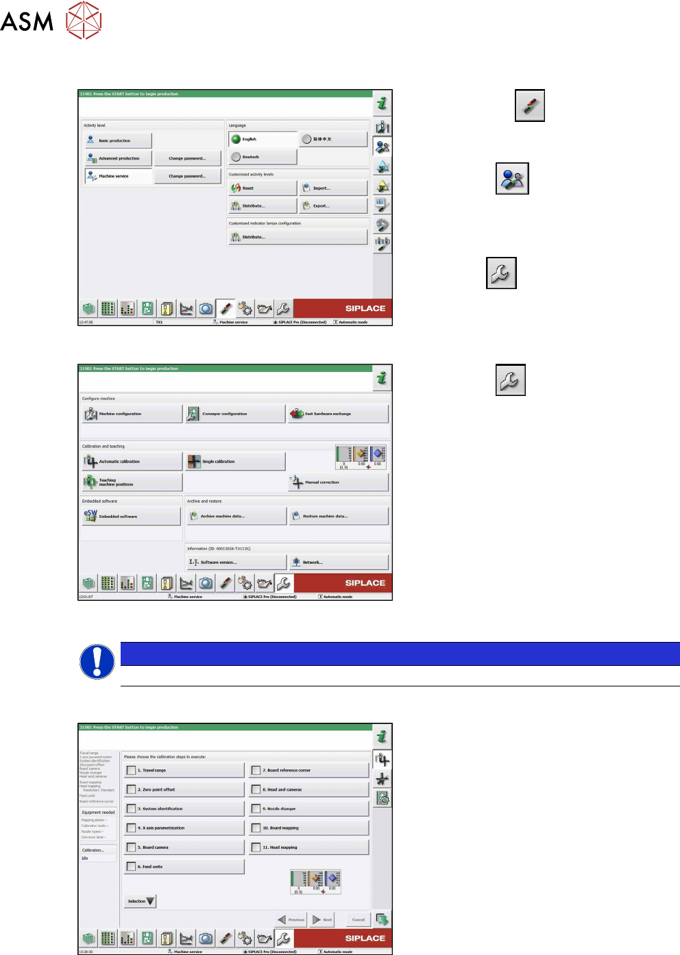
Fig.116: Select operator level
► Click on the
button, to open the
Configure, update and calibrate the
machine menu.
► Click the
button to open the
Check and set user settings menu.
► Switch over to the operator level Ma-
chine service.
ð The
button will appear.
Fig.117: Service menu
► Click the
button to enter the Ser-
vice menu.
► Click the Automatic calibration but-
ton.
NOTICE
With station software 712.0, the user interface of the Automatic calibration has changed.
Up to SW 711.x
Fig.118: Automatic calibration
► Choose Heads and cameras.
► Choose the Next button.
Follow the instructions on the next pages:
► On the next page, select the gantries
on which the heads to be calibrated are
located and then click on the Next but-
ton.
► The next step is to check the calibration
conditions (nozzle, calibration tool etc.).
Follow the instructions provided.
After this step, the calibration will begin. All
required intermediate steps (head height
etc.) will be performed automatically.
11 Software functions
11.1 Calibration
Service Manual SIPLACE SpeedStar (C&P20 P2) 01/2019 83
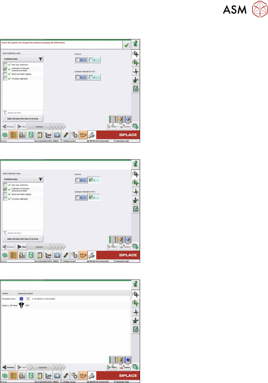
From SW 712.x
Fig.119: Combined steps view
► On the left-hand side, under Combined
steps, select the check box Cali-
bration of fiducials, cameras and
heads.
► If you chose Display all steps on the
left-hand side, choose Calibration of
cameras and heads.
► Under Gantries, select the location. For
a TX machine, always location 1.
► Choose Next.
Fig.120: Prerequisites view
Prerequisites view.
► Check the preconditions and choose
Start to start the calibration.
Fig.121: Calibration steps and status view
Calibration steps and status view.