00198608-02_SM_CP20P2_Kunde_EN.pdf - 第84页
11 Software functions 11.1 Calibration 84 Service Manual SIPLACE SpeedStar (C&P20 P2) 01/2019 Fig.122: Results view ► Choose Results to display detailled in- formation (important in case of an error). Fig.123: Save…
11 Software functions
11.1 Calibration
Service Manual SIPLACE SpeedStar (C&P20 P2) 01/2019 83
From SW 712.x
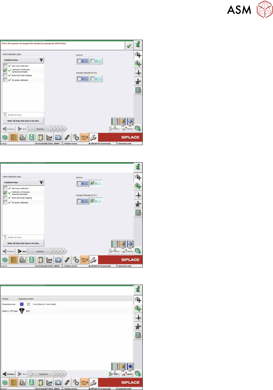
Fig.119: Combined steps view
► On the left-hand side, under Combined
steps, select the check box Cali-
bration of fiducials, cameras and
heads.
► If you chose Display all steps on the
left-hand side, choose Calibration of
cameras and heads.
► Under Gantries, select the location. For
a TX machine, always location 1.
► Choose Next.
Fig.120: Prerequisites view
Prerequisites view.
► Check the preconditions and choose
Start to start the calibration.
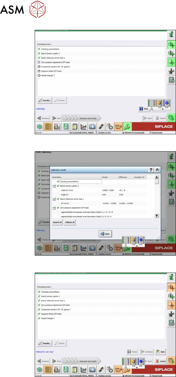
Fig.121: Calibration steps and status view
Calibration steps and status view.
11 Software functions
11.1 Calibration
84 Service Manual SIPLACE SpeedStar (C&P20 P2) 01/2019
Fig.122: Results view
► Choose Results to display detailled in-
formation (important in case of an
error).
Fig.123: Save view
► Choose Save after successful cali-
bration.
Fig.124: Save button
► Choose the Save button.
ð Calibration has finished.
11 Software functions
11.2 Zero point correction for the star and Z axis
Service Manual SIPLACE SpeedStar (C&P20 P2) 01/2019 85
11.2 Zero point correction for the star and Z axis
11.2.1 Transferring the head specific data (from SW701)
NOTICE
Fast Hardware Exchange
If a head exchange is carried out with the FHE function, the head specific data will be auto-
matically transferred to the machine data.
Checking and, if required, transferring head-specific data manually
ü If the zero point data (EPROM and station) are not correct, this will be shown.
If zero points need to be transferred manually, this must be done before the reference run. A
reference run can not be performed with incorrect values.
► Switch over to operator level SIPLACE (customer).
► Click the
button.
► Click the
button.
► Select the relevant head.
► Click on the
button for the Z axis or the button for the star axis.
This is where the axis data (Z and star axes) can be written from the head EPROM to the machine
data.
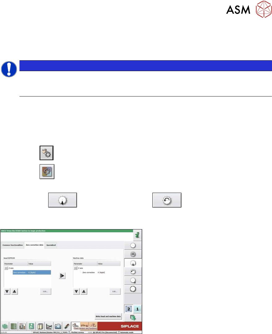
Fig.125: Zero correction data
► Go to the Zero correction datatab .
► Use the arrow button of the head EEP-
ROM to transfer the data to the
machine data.
► After correcting the parameters, click
on the Write head and machine dat-
abutton.
► If necessary, repeat this setting for the Z or star axis.