00198608-02_SM_CP20P2_Kunde_EN.pdf - 第85页
11 Software functions 11.2 Zero point correction for the star and Z axis Service Manual SIPLACE SpeedStar (C&P20 P2) 01/2019 85 11.2 Zero point correction for the star and Z axis 11.2.1 Transferring the head specific…
11 Software functions
11.1 Calibration
84 Service Manual SIPLACE SpeedStar (C&P20 P2) 01/2019
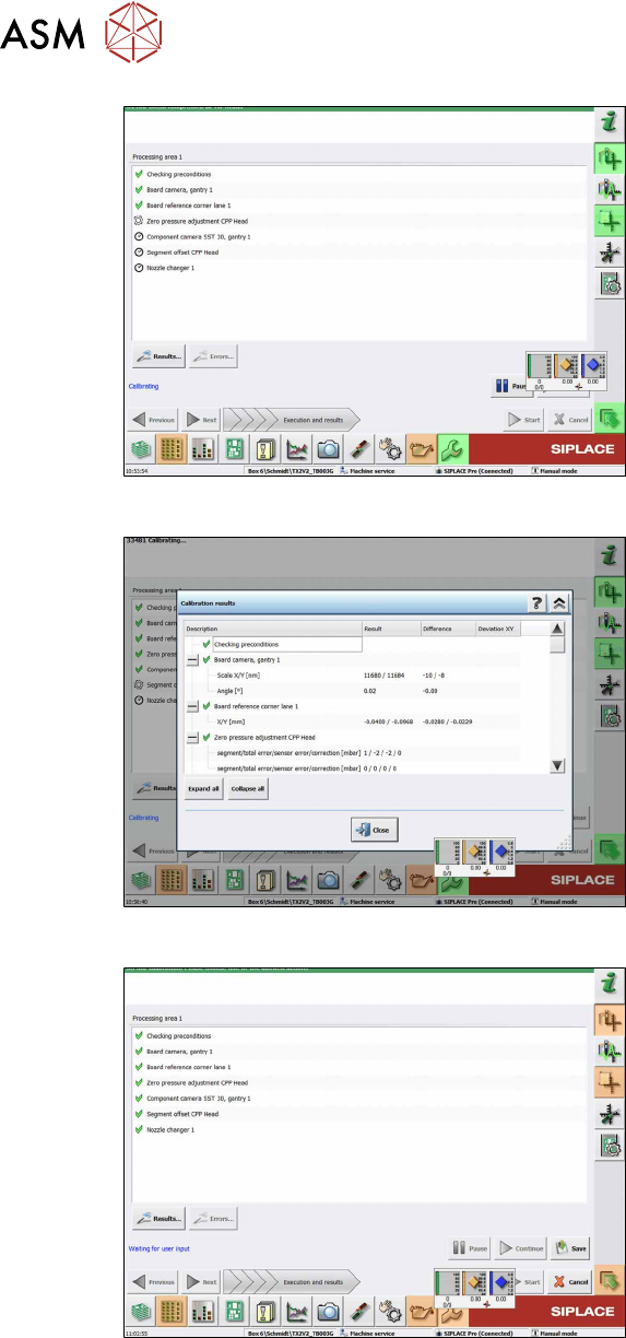
Fig.122: Results view
► Choose Results to display detailled in-
formation (important in case of an
error).
Fig.123: Save view
► Choose Save after successful cali-
bration.
Fig.124: Save button
► Choose the Save button.
ð Calibration has finished.
11 Software functions
11.2 Zero point correction for the star and Z axis
Service Manual SIPLACE SpeedStar (C&P20 P2) 01/2019 85
11.2 Zero point correction for the star and Z axis
11.2.1 Transferring the head specific data (from SW701)
NOTICE
Fast Hardware Exchange
If a head exchange is carried out with the FHE function, the head specific data will be auto-
matically transferred to the machine data.
Checking and, if required, transferring head-specific data manually
ü If the zero point data (EPROM and station) are not correct, this will be shown.
If zero points need to be transferred manually, this must be done before the reference run. A
reference run can not be performed with incorrect values.
► Switch over to operator level SIPLACE (customer).
► Click the
button.
► Click the
button.
► Select the relevant head.
► Click on the
button for the Z axis or the button for the star axis.
This is where the axis data (Z and star axes) can be written from the head EPROM to the machine
data.
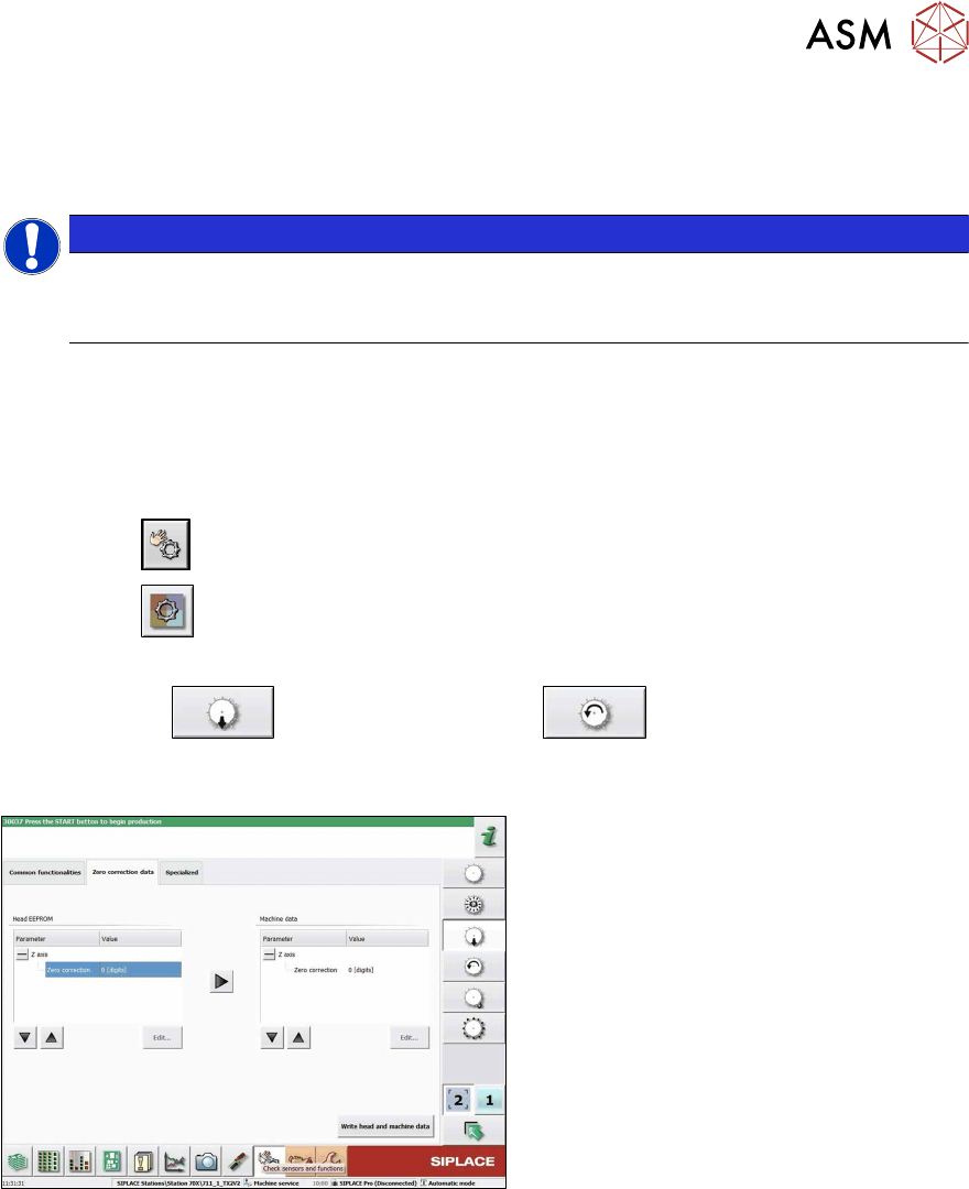
Fig.125: Zero correction data
► Go to the Zero correction datatab .
► Use the arrow button of the head EEP-
ROM to transfer the data to the
machine data.
► After correcting the parameters, click
on the Write head and machine dat-
abutton.
► If necessary, repeat this setting for the Z or star axis.
11 Software functions
11.3 Optical Nozzle Query (Nozzle Scanning)
86 Service Manual SIPLACE SpeedStar (C&P20 P2) 01/2019
11.3 Optical Nozzle Query (Nozzle Scanning)
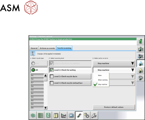
Fig.126: Nozzle scan
The nozzle scan can be enabled or disabled
in the software. Different scanning levels
and the corresponding actions for the errors
in individual nozzle types can be defined.
11.4 Calibrating the digital PRV
The digital PRV is part of the placement head and generates the vacuum and the blast air for the
pickup and placement process. The zero point calibration of the digital PRV must be performed on
initial startup by the customer and then checked again after replacement of the digital PRV or the
placement head and recalibrated if necessary.
The zero correction adjusts the pressure control valve to the ambient pressure.
11.5 Zero Point Calibration of Pressure Control Valve
The initialization (zero correction) of the pressure control valve (PRV) is performed at the same
time as the machine reference run.
To allow for the pressure control valve to work optimally, perform the following calibration steps in
the station software.
Perform this calibration in the following cases:
●
When exchanging the pressure control valve
●
When exchanging the placement head
●
When removing the placement head for maintenance and installing that same one afterwards
●
When error message 42466 is issued: Pressure control valve did not attain pressure threshold
for starting the Z axis.
Performing the calibration
ü Make sure that a calibration nozzle 6235 is inserted in segment 1 of the placement head.
► Switch over to the operator level Machine Service.