00197295-01_UM_D4i_SR605_EN.pdf - 第104页
3 Technical data for the machine User manual SIPLACE D4i 3.7 PCB conveyor system From software version SR.605.03 SP2 10/2012 EN edition 104 3.7 PCB conveyor system The machine is supplied with a PCB singl e conveyor as s…

User manual SIPLACE D4i 3 Technical data for the machine
From software version SR.605.03 SP2 10/2012 EN edition 3.6 Gantry system
103
The Y axis essentially consists of the following main modules:
– Y axis linear drive with permanent magnet (item 6 in Fig. 3.6 - 3
, page 102) and adapter
plate (item 8 in Fig. 3.6 - 3
, page 102)
– Y axis guide system (item 5 in Fig. 3.6 - 3
, page 102)
– Y axis measuring system (item 7 in Fig. 3.6 - 3
, page 102)
The Y axis is driven by a linear motor. The secondary part of the drive is made up of permanent
magnets and is mounted on the machine frame. The primary part is bolted to the gantry (adapter
plate). An anti-crash circuit prevents the traversing paths of the gantries meeting.
3.6.5 Technical data for the Y axis
Drive Direct, linear motor
Maximum speed 2.5 m/s
Traversing path of the gantries calculated from
the center of the machine
Gantry 1 - 688.5 mm
Gantry 2 - 768.5 mm
Gantry 3 - 688.5 mm
Gantry 4 - 768.5 mm
Distance measuring system Metal linear scale
Scale length 1530 mm
Resolution 1 µm
3 Technical data for the machine User manual SIPLACE D4i
3.7 PCB conveyor system From software version SR.605.03 SP2 10/2012 EN edition
104
3.7 PCB conveyor system
The machine is supplied with a PCB single conveyor as standard. The PCB dual conveyor is avail-
able as an option from the factory (see Section 3.7.6
, page 112). The left or the right side of the
PCB conveyor can be used as the stationary side, as required.
The conveyor belts are driven by DC motors. There is a lifting table for clamping the PCBs in each
processing area. The PCB conveyor width can either be set from the user interface or preset in
the placement program.
3.7.1 Structure
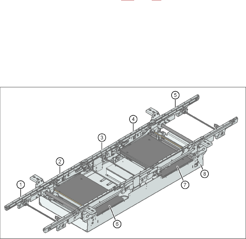
3.7.1.1 Structure of the PCB single conveyor
3
Fig. 3.7 - 1 Structure of the PCB single conveyor
(1) Input conveyor (5) Output conveyor
(2) Processing conveyor 1 (6) Lifting table 1
(3) Intermediate conveyor (7) Lifting table 2
(4) Processing conveyor 2 (8) Assembly tray
User manual SIPLACE D4i 3 Technical data for the machine
From software version SR.605.03 SP2 10/2012 EN edition 3.7 PCB conveyor system
105
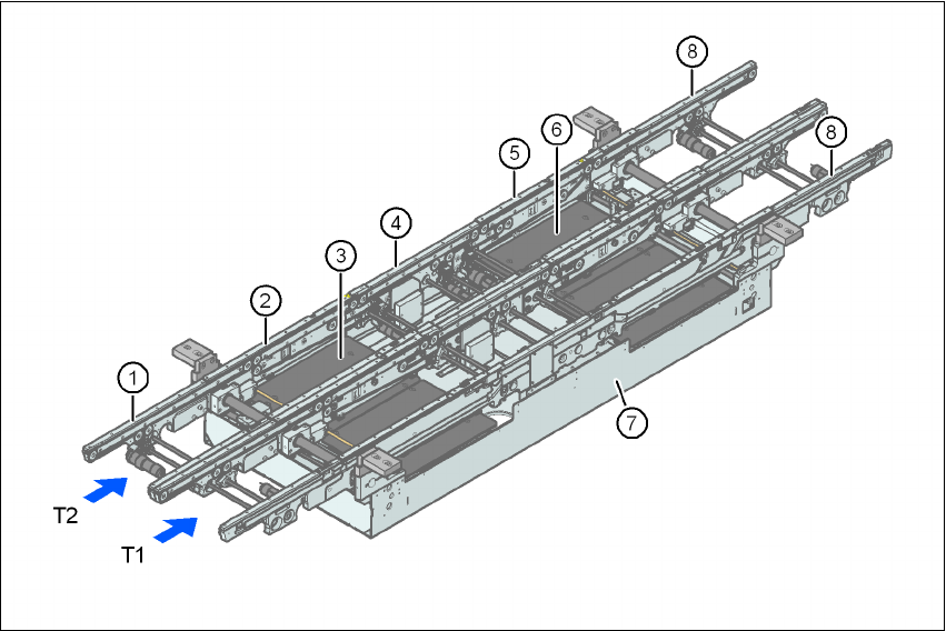
3.7.1.2 Structure of the PCB dual conveyor
3
Fig. 3.7 - 2 Structure of the PCB dual conveyor
3.7.2 Description
For placement, the PCB is clamped from below. The distance between the top of the PCB and the
placement head thus remains unchanged for each PCB, and is not dependent on the thickness of
the PCB. The placement rate is thus independent of the PCB thickness. The PCB fiducial center-
ing can also be optimized. Since the distance between the PCB surface and the PCB camera re-
mains the same, the PCB camera is always focused on the PCB surface with the same sharpness.
The PCB fiducial contours are optimally mapped on the CCD chip of the PCB camera.
The width of the circuit board conveyor is set and monitored by an integral control circuit. It can
be selected by calling up the program. The control circuit then actuates the stepping motors until
the desired width is reached. The width adjustment is therefore independent of other machine
components.
(1) Input conveyor (6) Lifting table 2
(2) Processing conveyor 1 (7) Assembly tray
(3) Lifting table 1 (8) Output conveyor
(4) Intermediate conveyor T1 Conveyor track 1
(5) Processing conveyor 2 T2 Conveyor track 2