00197295-01_UM_D4i_SR605_EN.pdf - 第106页
3 Technical data for the machine User manual SIPLACE D4i 3.7 PCB conveyor system From software version SR.605.03 SP2 10/2012 EN edition 106 The conveyo r height can be modif ied on the machine, th us allowing it to be in…
User manual SIPLACE D4i 3 Technical data for the machine
From software version SR.605.03 SP2 10/2012 EN edition 3.7 PCB conveyor system
105
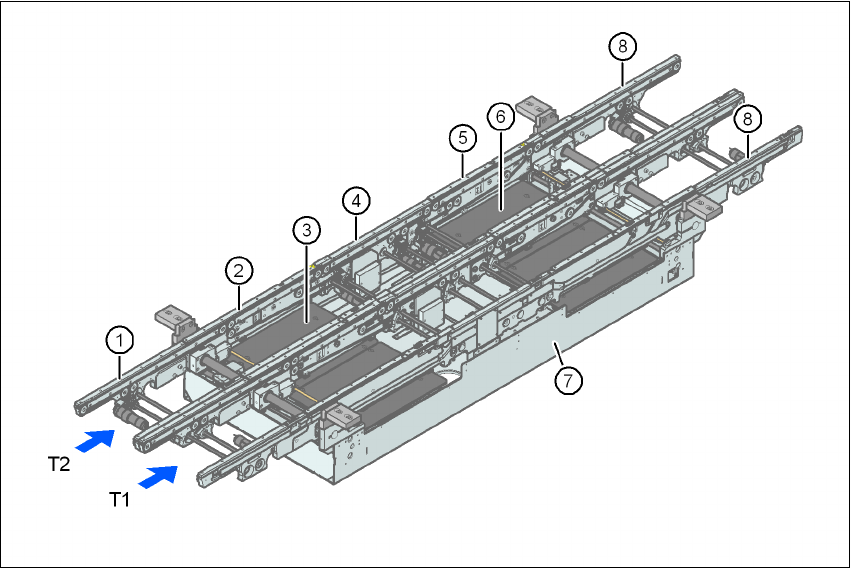
3.7.1.2 Structure of the PCB dual conveyor
3
Fig. 3.7 - 2 Structure of the PCB dual conveyor
3.7.2 Description
For placement, the PCB is clamped from below. The distance between the top of the PCB and the
placement head thus remains unchanged for each PCB, and is not dependent on the thickness of
the PCB. The placement rate is thus independent of the PCB thickness. The PCB fiducial center-
ing can also be optimized. Since the distance between the PCB surface and the PCB camera re-
mains the same, the PCB camera is always focused on the PCB surface with the same sharpness.
The PCB fiducial contours are optimally mapped on the CCD chip of the PCB camera.
The width of the circuit board conveyor is set and monitored by an integral control circuit. It can
be selected by calling up the program. The control circuit then actuates the stepping motors until
the desired width is reached. The width adjustment is therefore independent of other machine
components.
(1) Input conveyor (6) Lifting table 2
(2) Processing conveyor 1 (7) Assembly tray
(3) Lifting table 1 (8) Output conveyor
(4) Intermediate conveyor T1 Conveyor track 1
(5) Processing conveyor 2 T2 Conveyor track 2

3 Technical data for the machine User manual SIPLACE D4i
3.7 PCB conveyor system From software version SR.605.03 SP2 10/2012 EN edition
106
The conveyor height can be modified on the machine, thus allowing it to be integrated into lines
with a conveyor height of 830, 900, 930 or 950 mm.
The PCB conveyors communicate with the individual machines via the optional SMEMA interface
or the Siemens interface.
The fixed transport side can be located on the left or right for both the dual conveyor and the single
conveyor. With this conveyor, the fixed side can be switched from right to left and vice versa.
The circuit board conveyor is monitored and controlled with optical sensors. If the board has
reached placement area and passed the light barrier, it is braked. A laser light barrier determines
the position of the board. As soon as the circuit board has reached its target position, the conveyor
belt is stopped and the board is clamped from below.
3.7.3 Definition of conveyor tracks and transport modes
The right conveyor track (viewed in the transport direction) is designated "Conveyor 1" and the left
as "Conveyor 2" (see Fig. 3.7 - 4
, page 108).
3.7.3.1 Definition of the conveyor track width
3.7.3.2 Standard width
The standard width of the conveyor track is the maximum conveyor width defined by the desired
position of the stationary conveyor side. It is no more than 216 mm per track.
3.7.3.3 Overwide conveyor track
The conveyor track can be widened to 242 mm maximum by moving the stationary conveyor side
wall out of its normal position.
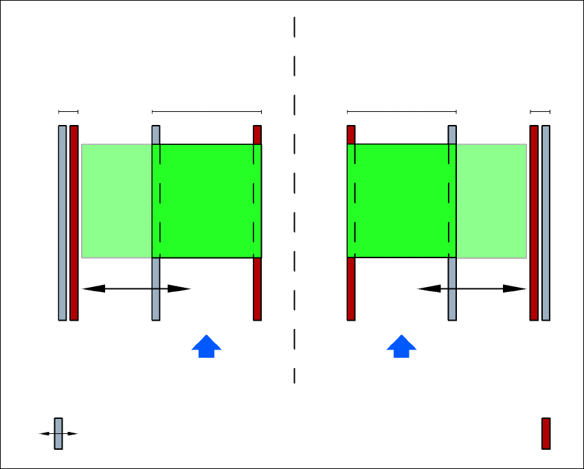
3.7.3.4 Dual conveyor in Single conveyor mode
The dual conveyor can be configured online to create a single conveyor. To do this, one conveyor
track is moved fully together and deactivated (see Fig. 3.7 - 3
, page 107). This gives a conveyor
track width of up to 380 mm.
User manual SIPLACE D4i 3 Technical data for the machine
From software version SR.605.03 SP2 10/2012 EN edition 3.7 PCB conveyor system
107
3
Fig. 3.7 - 3 Flexible dual conveyor in Single conveyor mode
3.7.3.5 Transport modes
The flexible dual conveyor can be used in two modes:
– Synchronous transport mode
– Asynchronous transport mode
3.7.3.6 Asynchronous transport mode
Description 3
In asynchronous mode, only one PCB in a transport track is processed. At the same time, another
PCB in the second transport track is moved into the placement position. This saves the full con-
veying time of one PCB, thus considerably increasing performance, particularly for PCBs with a
short cycle time.
Once the machine has received the job data (panel, set-up), the PCBs on the feeding belts are
continuously transported to the available processing belt (provided that the processing belt is free)
Dual conveyor with widened conveyor track 2
(stationary conveyor side wall on left)
Conveyor track 2
deactivated
Conveyor track 1 Conveyor track 2 Conveyor track 1
deactivated
PCB transport direction PCB transport direction
Stationary conveyor side wall
Dual conveyor with widened conveyor track 1
(stationary conveyor side wall on right)
Movable conveyor side wall