00197295-01_UM_D4i_SR605_EN.pdf - 第131页
User manual SIPLACE D4i 3 Technical data for the machine From software version SR.605.03 SP2 10/2012 EN edition 3.9 Feeder modules 131 3.9.13.2 T echnical dat a 3 3 3 3.9.13.3 Parameters for surf t ape feeder modules The…
3 Technical data for the machine User manual SIPLACE D4i
3.9 Feeder modules From software version SR.605.03 SP2 10/2012 EN edition
130
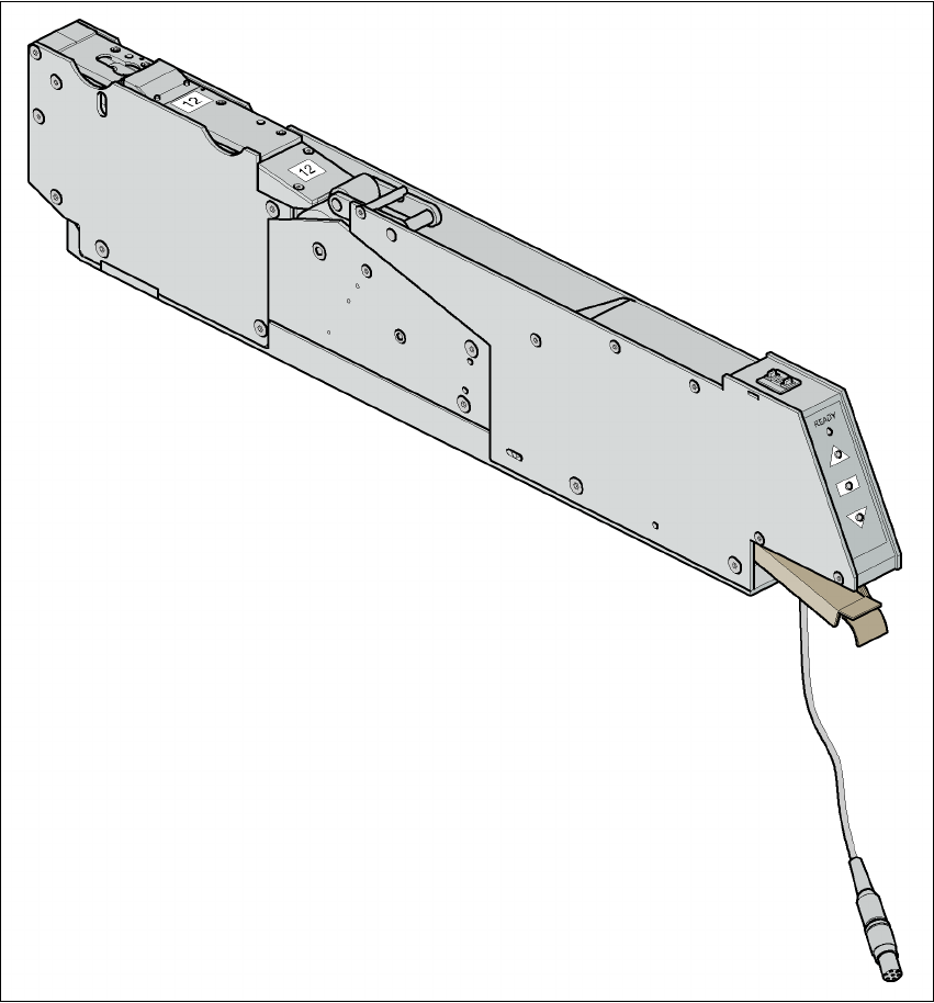
3.9.13 Surf tape feeder module
3.9.13.1 Overview
For placing bare dies, you will need the surf tape feeder module for feeding components. There
are versions of these feeder modules for 8 mm tapes and 12 or 16 mm tapes.
3
Fig. 3.9 - 8 Surf tape feeder module
Handling of the feeder module is described in the operating instructions for feeder modules.

User manual SIPLACE D4i 3 Technical data for the machine
From software version SR.605.03 SP2 10/2012 EN edition 3.9 Feeder modules
131
3.9.13.2 Technical data
3
3
3
3.9.13.3 Parameters for surf tape feeder modules
The parameters for the surf tape feeder module can be modified on the SIPLACE Pro computer.
Tape widths 8/12/16 mm
Recommended tape and component
sizes
8 mm: for 1 x 1 mm² - 2.3 x 2.3 mm² components
12 mm: for 2.3 x 2.3 mm² - 5 x 5 mm² components
16 mm: for 3.8 x 3.8 mm² - 9.5 x 9.5 mm² compo-
nents
Packaging accuracy of the bare die on
the surf tape
Bare die size up to 2.3 x 2.3 mm²: +/- 100 µm, 6
Bare die size over 2.3 x 2.3 mm²: +/- 200 µm, 6
(related to the center of the pocket)
Required distance between the edges of
the bare dies to the tape pocket Min. 0.4 mm
Pusher needle Single or triple needle depending on the die size
Tape material Metric
Tape standard IEC 286-3, DIN-IEC-286, EIA 481, and JIS C 0806
Tape reel diameter 7" to 15"
Footprint of the feeder module 1 location on the component table
3 Technical data for the machine User manual SIPLACE D4i
3.10 Component trolley From software version SR.605.03 SP2 10/2012 EN edition
132
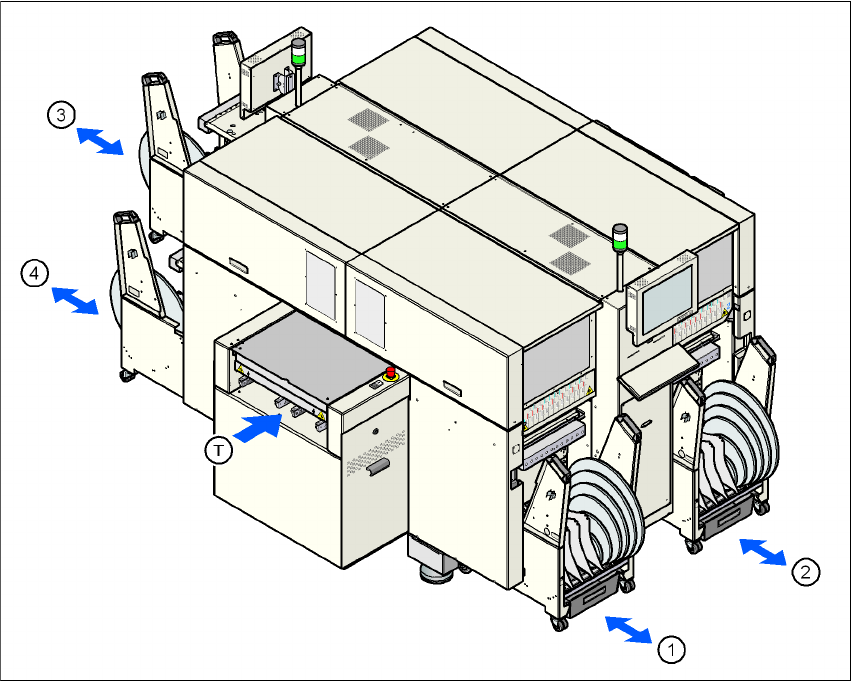
3.10 Component trolley
Item no. 00119821-xx CO trolley HS feeder, D4i
Up to four component trolleys can be docked into SIPLACE D4i machines. The locations are num-
bered as shown in the diagram below.
3
Fig. 3.10 - 1 Locations for the component trolleys
(1) Location 1
(2) Location 2
(3) Location 3
(4) Location 4
(T) PCB direction of travel
The component trolleys are stand-alone modules that can be set up with feeders at an external
set-up area. This means that the production process only has to be interrupted briefly in order to
change the component trolley.