00197295-01_UM_D4i_SR605_EN.pdf - 第134页
3 Technical data for the machine User manual SIPLACE D4i 3.10 Component trolley From software version SR.605.03 SP2 10/2012 EN edition 134 3.10.1 Structure The compone nt trolley essentially con sists of the chassis, th …
User manual SIPLACE D4i 3 Technical data for the machine
From software version SR.605.03 SP2 10/2012 EN edition 3.10 Component trolley
133
PLEASE NOTE: 3
At external set-up positions, you will need an external power supply for the component trolley
(see Section 3.10.5, page 137).
3
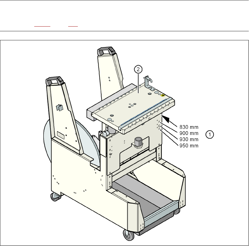
Fig. 3.10 - 2 Component trolley with a PCB conveyor height of 950 mm
3
(1) Holes for the conveyor heights of 830 to 950 mm
(2) Component table
Properties
– The trolleys move easily.
– The component trolley is fixed so precisely to the machine that it is even suitable for process-
ing 01005 components.
– The component trolley can be adjusted to PCB conveyor heights of 830 mm, 900 mm, 930
mm and 950 mm in just a few simple actions.
– The tape container can hold tape reels with a diameter of up to 15" (optional up to 19").
3 Technical data for the machine User manual SIPLACE D4i
3.10 Component trolley From software version SR.605.03 SP2 10/2012 EN edition
134
3.10.1 Structure
The component trolley essentially consists of the chassis, the component table for holding the
feeder modules, the communication unit, tape reel container and the waste container.
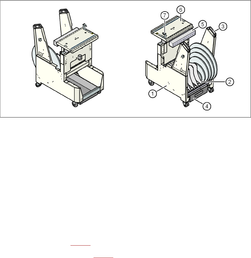
Fig. 3.10 - 3 Component trolley: front and back view
(1) Chassis
(2) Tape reel container
(3) Handle
(4) Waste tape container
(5) Communication unit
(6) Component table
(7) Button for lowering the component table
3.10.2 Description
The chassis (item 1 in Fig. 3.10 - 3) runs smoothly and is easy to maneuver.
The component table (item 6 in Fig. 3.10 - 3
) has a capacity of up to 12 locations for 30 mm wide
feeder modules. The feeder modules are mechanically centered on the table using centering pins
and centering balls. The bulk case feeder modules are supplied with compressed air via a sepa-
rate compressed air bar.
The interface is connected to the machine using a cable. The power supply, communication and
EMERGENCY STOP circuits are routed via this cable. The compressed air supply for the bulk
case feeder module and the lifting mechanism also pass via this interface.

User manual SIPLACE D4i 3 Technical data for the machine
From software version SR.605.03 SP2 10/2012 EN edition 3.10 Component trolley
135
NOTE ON OPERATIONAL SAFETY 3
All component trolleys must be docked on the machine in order to operate it. If they are not, the
machine stays in EMERGENCY STOP status. The placement process is interrupted.
The communication interface (item 5 in Fig. 3.10 - 3
, page 134) supplies the necessary voltages
and control signals to the feeder modules.
The tape reel container (item 4 in Fig. 3.10 - 3
, page 134) holds tape reels up to 19" (483 mm).
The pull-out waste tape container (item 4 in Fig. 3.10 - 3
, page 134) can be found beneath the
chassis. The cut waste tape travel down a chute into the waste container, which must be regularly
emptied.
3.10.3 Technical data
3
3
Length
Width
Height
830 mm PCB conveyor height
900 mm PCB conveyor height
930 mm PCB conveyor height
950 mm PCB conveyor height
753 mm
470 mm
922 mm
992 mm
1022 mm
1042 mm
Height of bottom edge of table bed for
830 mm PCB conveyor height
900 mm PCB conveyor height
930 mm PCB conveyor height
950 mm PCB conveyor height
680 mm
750 mm
780 mm
802 mm
PCB conveyor height 830 mm ± 15 mm (standard)
900 mm ± 15 mm (option)
930 mm ± 15 mm (option)
950 mm ± 15 mm (SMEMA option)
Weight
without feeder modules
with feeder modules at all locations
74 kg
102 kg
Reel diameter
standard
maximum
up to 432 mm (17")
483 mm (19")
Locations for feeder modules max. 12
Changeover time less than 1 min.