00197295-01_UM_D4i_SR605_EN.pdf - 第149页
User manual SIPLACE D4i 4 Setting up and commissioning From software version SR.605.03 SP2 10/2012 EN edition 4.2 Infrastructure a t the installation location 149 4.2.3.2 Compressed air connection on the machine 4 Fig. 4…

4 Setting up and commissioning User manual SIPLACE D4i
4.2 Infrastructure at the installation location From software version SR.605.03 SP2 10/2012 EN edition
148
4.2 Infrastructure at the installation location
4.2.1 Recommendations concerning the quality of the foundation
The foundation for the machine should be flat and level since dynamic forces can generate vibra-
tions at the installation site when the machine is in use. The magnitude of the vibrations depends
on the foundation construction. The following are suitable provided that the floor loading parame-
ters, etc., are not exceeded:
– Reinforced concrete ceiling constructions, e.g. ceilings in production halls
– Reinforced concrete floor slabs, e.g. concrete floors in production halls without a basement
– Rooms with double floors, provided that a stable foundation is included in the space between
them. The same set-up conditions apply to this intermediate foundation, which can be made
from steel girders or concrete.
4.2.2 Machine weight and floor loading
The machine weight and floor loading values can be found in Section 3.3.1, page 90.
4.2.3 Compressed air supply
4.2.3.1 Checking the compressed air supply
Check that the compressed air supply conforms to the prescribed machine specifications (see ta-
ble in Section 3.2
, page 88).
PLEASE NOTE: 4
The document entitled "Network configuration (electrical and compressed air) for SMD systems
on the customer's premises", item no. 00191409-xx, describes the action that can be taken to
meet the required specifications.
→ Record the compressed air characteristics at the installation location.
User manual SIPLACE D4i 4 Setting up and commissioning
From software version SR.605.03 SP2 10/2012 EN edition 4.2 Infrastructure at the installation location
149
4.2.3.2 Compressed air connection on the machine
4
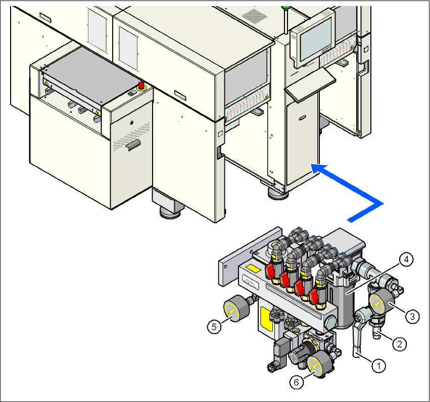
Fig. 4.2 - 1 Compressed air line connection
(1) Stop valve in the "OPEN" position
(2) Compressed air connection
(3) Manometer for the input pressure
Desired pressure: 0.55 - 1.0 MPa (5.5 - 10 bar), display range: 0 - 1.2 MPa (0 - 12 bar)
(4) Compressed air filter
(5) Manometer for the gantry distributor supply pressure
Desired pressure: 0.51 ± 0.01 MPa (5.1 ± 0.1 bar), display range: 0 - 1.2 MPa (0 - 12 bar)
(6) Manometer for the bulk case feeder modules supply pressure
Desired pressure: 0.25 ± 0.05 MPa (2.5 ± 0.5 bar), display range: 0 - 0.6 MPa (0 - 6 bar)
4 Setting up and commissioning User manual SIPLACE D4i
4.2 Infrastructure at the installation location From software version SR.605.03 SP2 10/2012 EN edition
150
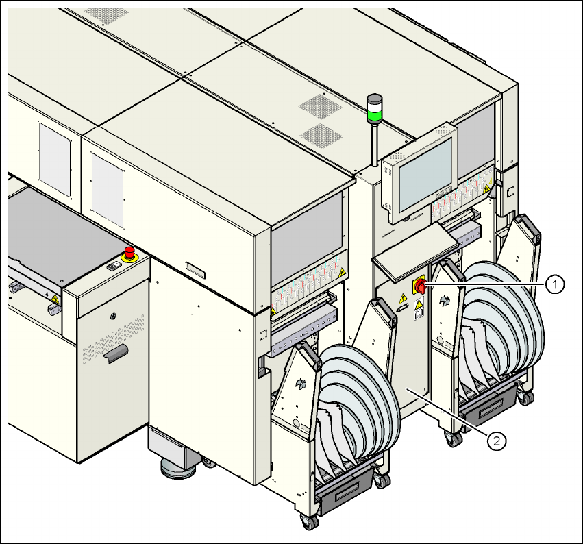
4.2.4 Main power supply
4
Fig. 4.2 - 2 Position of the power supply on the machine
4
(1) Main power switch secured to prevent switching on again
(2) Cover