00197295-01_UM_D4i_SR605_EN.pdf - 第153页
User manual SIPLACE D4i 4 Setting up and commissioning From software version SR.605.03 SP2 10/2012 EN edition 4.2 Infrastructure a t the installation location 153 4.2.4.4 Connecting the power supply c able 4 Fig. 4.2 - 4…
4 Setting up and commissioning User manual SIPLACE D4i
4.2 Infrastructure at the installation location From software version SR.605.03 SP2 10/2012 EN edition
152
WARNING 4
The electrical cables to each individual machine and to the installed options (e.g. vacuum pump)
must be clearly identified and there must be no doubt as to their allocation. The regulations of the
country in which the machine is operated apply.
4
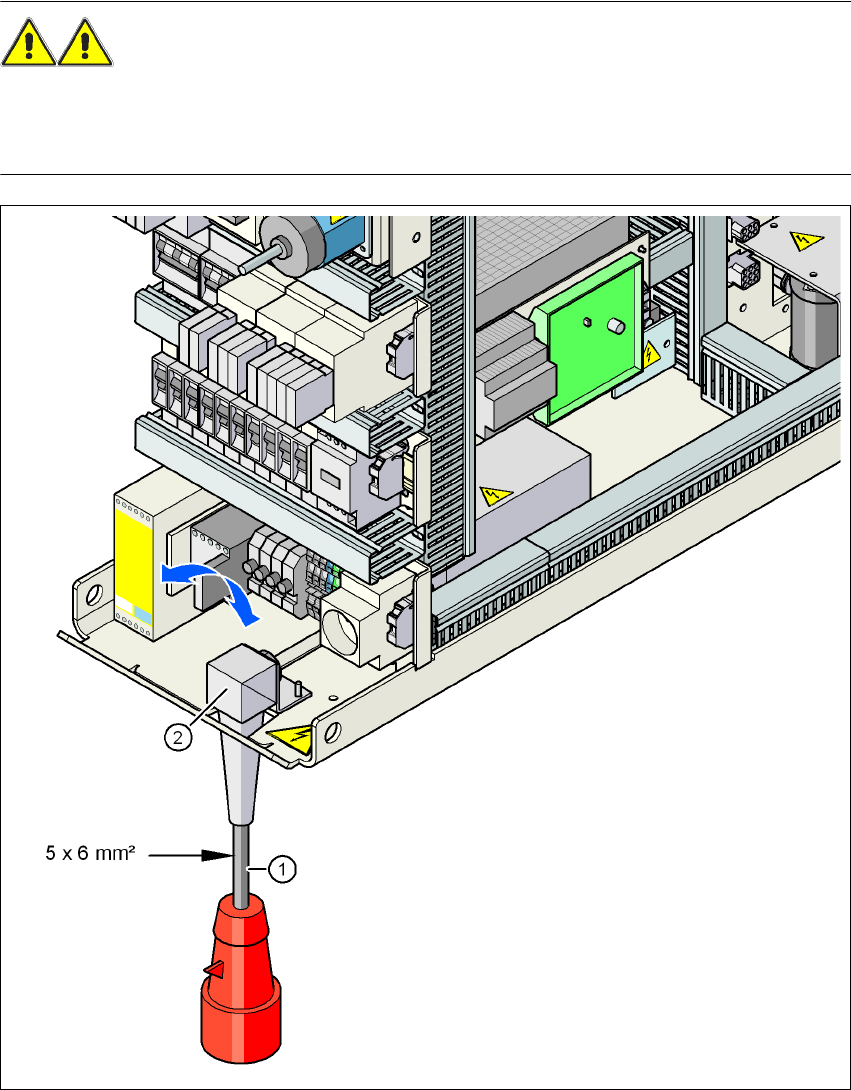
Fig. 4.2 - 3 Cross-section of the main power cable
(1) Power supply cable
(2) Angle for the cable gland
User manual SIPLACE D4i 4 Setting up and commissioning
From software version SR.605.03 SP2 10/2012 EN edition 4.2 Infrastructure at the installation location
153
4.2.4.4 Connecting the power supply cable
4
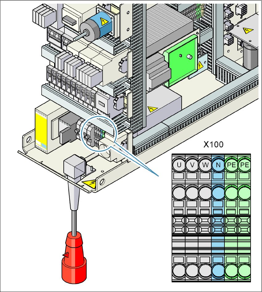
Fig. 4.2 - 4 Terminal panel for connecting the power cable
(U) Three-phase
(V) Three-phase
(W) Three-phase
(N) Neutral conductor
(PE) Protective earth wire
(X100) Infeed terminals
4 Setting up and commissioning User manual SIPLACE D4i
4.2 Infrastructure at the installation location From software version SR.605.03 SP2 10/2012 EN edition
154
→ Crimp a ferrule onto each end of the wire.
→ Loosen the nuts on the angled cable gland (item 2 in Fig. 4.2 - 3
).
→ Fold up the angled cable gland.
→ Feed the power supply cable through the angled cable gland to the terminal panel X100 (see
X100 in Fig. 4.2 - 4
).
→ Connect the cable to the terminal and ensure that it has a sufficient bending radius. The wires
must not be kinked.
→ Fold up the angled cable gland (item 2 in Fig. 4.2 - 3
) and tighten the nuts hand-tight.
4.2.4.5 Checking connections to the primary side of the three-phase transformer T1
The primary side of the three-phase transformer T1 must be configured for the respective supply
voltage.
→ Therefore check at the terminal block (see Fig. 4.2 - 5
) to see whether the primary side of the
three-phase transformer T1 has been correctly connected for the respective supply voltage.
4
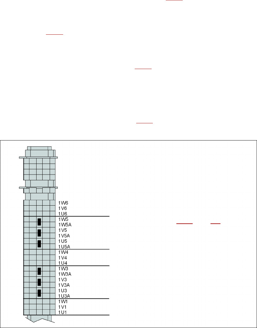
Fig. 4.2 - 5 Terminal block for the primary side of the three-phase transformer T1
See item 3 in Fig. 4.2 - 6, page 155 for the
position of the terminal block
3 x 204 VAC
3 x 230 VAC
3 x 380 VAC
3 x 400 VAC
3 x 415 VAC