00197295-01_UM_D4i_SR605_EN.pdf - 第154页
4 Setting up and commissioning User manual SIPLACE D4i 4.2 Infrastructure at the installation location From software version SR.605.03 SP2 10/2012 EN edition 154 → Crimp a ferrule onto each end of the wire. → Loosen the …
User manual SIPLACE D4i 4 Setting up and commissioning
From software version SR.605.03 SP2 10/2012 EN edition 4.2 Infrastructure at the installation location
153
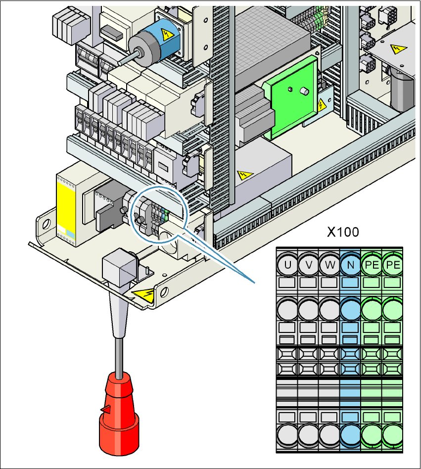
4.2.4.4 Connecting the power supply cable
4
Fig. 4.2 - 4 Terminal panel for connecting the power cable
(U) Three-phase
(V) Three-phase
(W) Three-phase
(N) Neutral conductor
(PE) Protective earth wire
(X100) Infeed terminals
4 Setting up and commissioning User manual SIPLACE D4i
4.2 Infrastructure at the installation location From software version SR.605.03 SP2 10/2012 EN edition
154
→ Crimp a ferrule onto each end of the wire.
→ Loosen the nuts on the angled cable gland (item 2 in Fig. 4.2 - 3
).
→ Fold up the angled cable gland.
→ Feed the power supply cable through the angled cable gland to the terminal panel X100 (see
X100 in Fig. 4.2 - 4
).
→ Connect the cable to the terminal and ensure that it has a sufficient bending radius. The wires
must not be kinked.
→ Fold up the angled cable gland (item 2 in Fig. 4.2 - 3
) and tighten the nuts hand-tight.
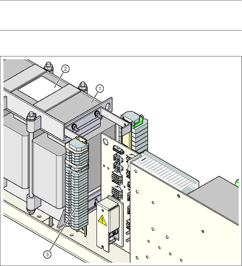
4.2.4.5 Checking connections to the primary side of the three-phase transformer T1
The primary side of the three-phase transformer T1 must be configured for the respective supply
voltage.
→ Therefore check at the terminal block (see Fig. 4.2 - 5
) to see whether the primary side of the
three-phase transformer T1 has been correctly connected for the respective supply voltage.
4
Fig. 4.2 - 5 Terminal block for the primary side of the three-phase transformer T1
See item 3 in Fig. 4.2 - 6, page 155 for the
position of the terminal block
3 x 204 VAC
3 x 230 VAC
3 x 380 VAC
3 x 400 VAC
3 x 415 VAC
User manual SIPLACE D4i 4 Setting up and commissioning
From software version SR.605.03 SP2 10/2012 EN edition 4.2 Infrastructure at the installation location
155
PLEASE NOTE 4
The Japanese supply network (3 x 200 VAC) and supply networks in the USA (3 x 208 VAC) are
connected to terminals for 3 x 204 VAC.
4
4
4
4
Fig. 4.2 - 6 Position of the terminal block with primary connections for the three-phase transformer T1
(1) Three-phase transformer T1
(2) Sign with the connection wiring diagram for the primary side
(3) Terminal block with primary connections for the three-phase transformer T1