00197295-01_UM_D4i_SR605_EN.pdf - 第194页
5 Tasks for the operating personnel User manual SIPLACE D4i 5.3 Note operating status indicator lamp From software version SR.605.03 SP2 10/2012 EN edition 194 5.2.3.2 Controls on the input and output s ides of the machi…

User manual SIPLACE D4i 5 Tasks for the operating personnel
From software version SR.605.03 SP2 10/2012 EN edition 5.2 Controls and displays
193
5.2.3 Ergonomic arrangement of the controls
Figure 5.2 - 1 on page 191 provides an overview of the position of the controls. They are subdi-
vided into the following groups:
Operator panel on the right-hand side (pneumatic unit) of the center console with 5
– LCD touchscreen
– Keyboard with trackball
– Start button, stop button
Operator panel on the left-hand side (power supply unit) of the center console with 5
– LCD touchscreen
– Keyboard with trackball
– Component counter
– Start button
– Stop button
– Main power switch
Input / output side of the PCB conveyor with 5
– EMERGENCY STOP button
– Start button, stop button
5.2.3.1 Controls on the machine's operator panels
The two operator panel have identical control functions.
Monitor, keyboard, start and stop buttons 5
There is a monitor and a keyboard on both sides of the machine.
The start and stop buttons are located beneath the keyboard. The on-screen dialog will occasion-
ally prompt you to activate certain actions using buttons, and this arrangement will make it easier
for you both to activate and to interactively control these actions.
Main power switch 5
The main power switch is part of the power module. It is located on the left-hand operator panel
viewed in the direction of PCB transport. It is located here because it is only needed for servicing
and preventive maintenance work and is therefore not subject to frequent use.
5 Tasks for the operating personnel User manual SIPLACE D4i
5.3 Note operating status indicator lamp From software version SR.605.03 SP2 10/2012 EN edition
194
5.2.3.2 Controls on the input and output sides of the machine
The controls on the input and output sides of the machine perform identical functions.
EMERGENCY STOP buttons, start and stop buttons 5
There is an EMERGENCY STOP button and start and stop buttons on both the input and output
sides of the PCB conveyor. This arrangement was adopted for the buttons because it enables
them to be reached quickly and easily from any position.
5.3 Note operating status indicator lamp
The indicator lamp is used to signal operating statuses and malfunctions of the machine.
5.3.1 Description of the functions
5
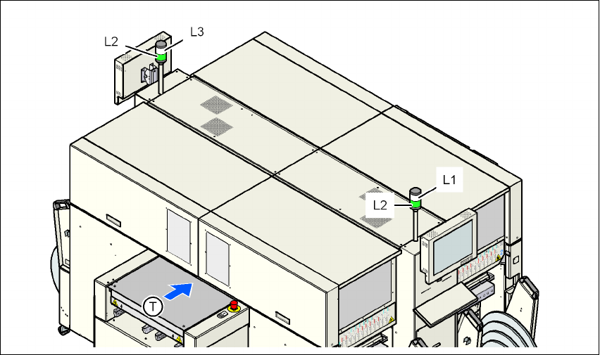
Fig. 5.3 - 1 Operating status indicator lamp
L1 Fault indicator lamp (white, right)
L2 Operating status indicator lamp (green, both lamps switched in parallel)
L3 Fault indicator lamp (white, left)
T Direction of PCB transport

User manual SIPLACE D4i 5 Tasks for the operating personnel
From software version SR.605.03 SP2 10/2012 EN edition 5.3 Note operating status indicator lamp
195
5.3.2 General operating statuses
– Operating status indicator lamp L2 (green) on continuously
The machine is in service.
– Operating status indicator lamp L2 (green) flashes
The machine is waiting for a PCB on the input belt or the machine is waiting until the output
belt is free.
– Right fault indicator lamp L1 (white) flashes
One or more tracks are empty on the right-hand side of the machine. The machine populates
the current PCB with the existing components.
– Left fault indicator lamp L3 (white) flashes
One or more tracks are empty on the left-hand side of the machine. The machine populates
the current PCB with the existing components.
– Right fault indicator lamp L1 (white ) on continuously - operating status lamp L2 (green) off
An error has occurred on the right-hand side of the machine -> the machine has stopped.
– Left fault indicator lamp L3 (white ) on continuously - operating status lamp L2 (green) off
An error has occurred on the left-hand side of the machine -> the machine has stopped.
– Both fault indicator lamps L1 and L3 (white) on continuously - operating status lamp L2
(green) off
An error has occurred that affects the entire machine -> the machine has stopped.
5
5
5.3.3 Programmed operating status displays
The following table shows the programmed operating status displays in the standard configuration
(version as supplied) and lists their meaning on the individual lamps of the main fault indicator.
The entries in the table next to "flashes" refer to the frequency with which the relevant lamp flashes
for a given event. The entry (1, 5), for example, can be explained as follows:
– The first number in the brackets indicates the time, expressed in 100 msec. intervals, for
which the fault indicator lamp is switched on, i.e. 1 x 100 ms in the above example.
– The second number in the brackets indicates the time, expressed in 100 msec. intervals, for
which the fault indicator lamp is switched off, i.e. 5 x 100 ms in the above example.
5
L1 (white)
(right lamp)
L2 (green) L3 (white)
(left lamp)
Meaning
Status display
flashes (1,10) flashes (7,7) flashes (1,10) Reference run
unchanged flashes (1,5) unchanged Waiting until axes in position