00197295-01_UM_D4i_SR605_EN.pdf - 第62页
2 Operational safety User manual SIPLACE D4i 2.6 Safety equipment From software version SR.605.03 SP2 10/2012 EN edition 62 2.6.2.2 Position of protective switches on the machine 2 Fig. 2.6 - 5 Position of protective swi…
User manual SIPLACE D4i 2 Operational safety
From software version SR.605.03 SP2 10/2012 EN edition 2.6 Safety equipment
61
2
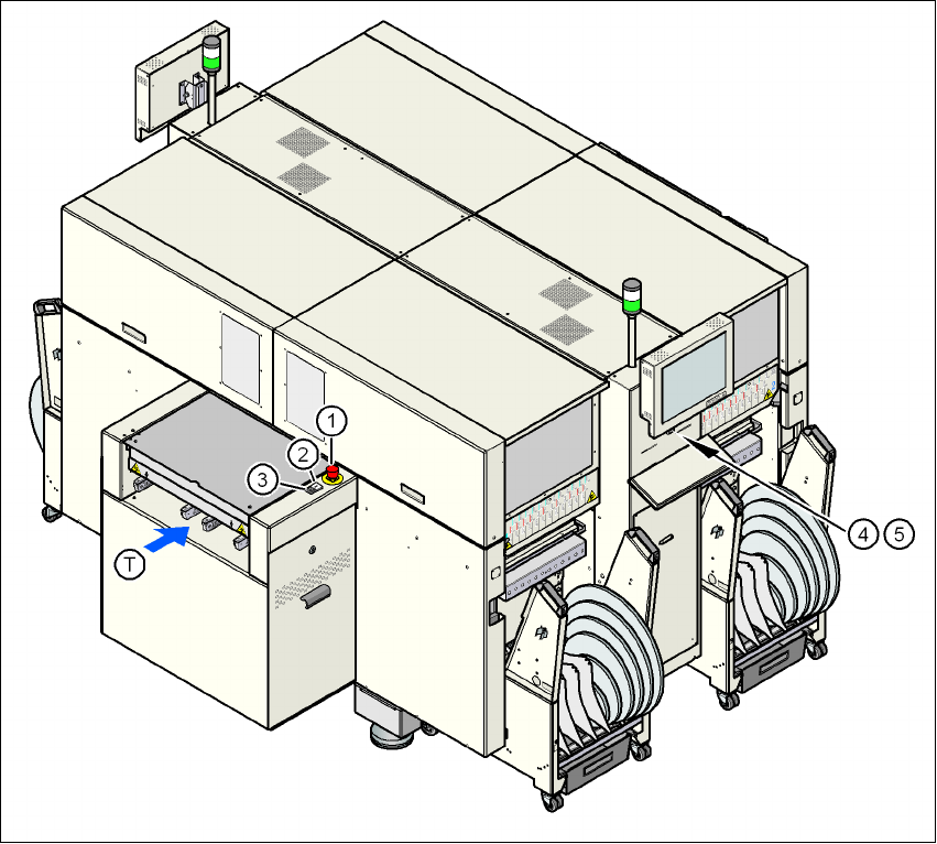
Fig. 2.6 - 4 Position of switches and buttons - View of the PCB input side
(1) EMERGENCY STOP button on the input side
(2) Start button (white) on the input side
(3) Stop button (white) on the input side
(4) Start button (white) on the operator panel on the compressed air unit side
(5) Stop button (black) on the operator panel on the compressed air unit side
(T) PCB transport direction
2 Operational safety User manual SIPLACE D4i
2.6 Safety equipment From software version SR.605.03 SP2 10/2012 EN edition
62
2.6.2.2 Position of protective switches on the machine
2
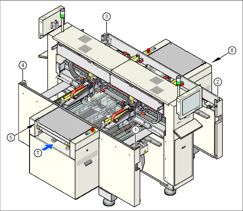
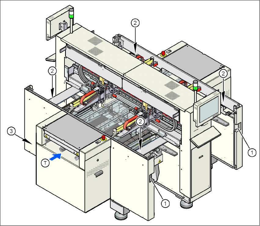
Fig. 2.6 - 5 Position of protective switches on the machine
2
(1) Protective cover switch, location 1
(2) Protective cover switch, location 2
(3) Protective cover switch, location 3
(4) Protective cover switch, location 4
(5) Protective switch for the cover flap on the PCB conveyor input side
(6) Protective switch for the cover flap on the PCB conveyor output side
(T) PCB transport direction
User manual SIPLACE D4i 2 Operational safety
From software version SR.605.03 SP2 10/2012 EN edition 2.6 Safety equipment
63
2.6.2.3 Position of control computer, connecting sockets and buttons for the component
trolley
2
Fig. 2.6 - 6 Control computer, connecting sockets and buttons for the component trolley
2
(1) Socket for connecting the component trolley
(2) Push-button for raising the component table, with the hinged cover flap over it
(3) Control computer
(T) PCB transport direction