00197295-01_UM_D4i_SR605_EN.pdf - 第93页
User manual SIPLACE D4i 3 Technical data for the machine From software version SR.605.03 SP2 10/2012 EN edition 3.3 Dimensions and weig ht 93 3.3.4 Maneuvering dist ance for the component trolley on the machine 3 Fig. 3.…
3 Technical data for the machine User manual SIPLACE D4i
3.3 Dimensions and weight From software version SR.605.03 SP2 10/2012 EN edition
92
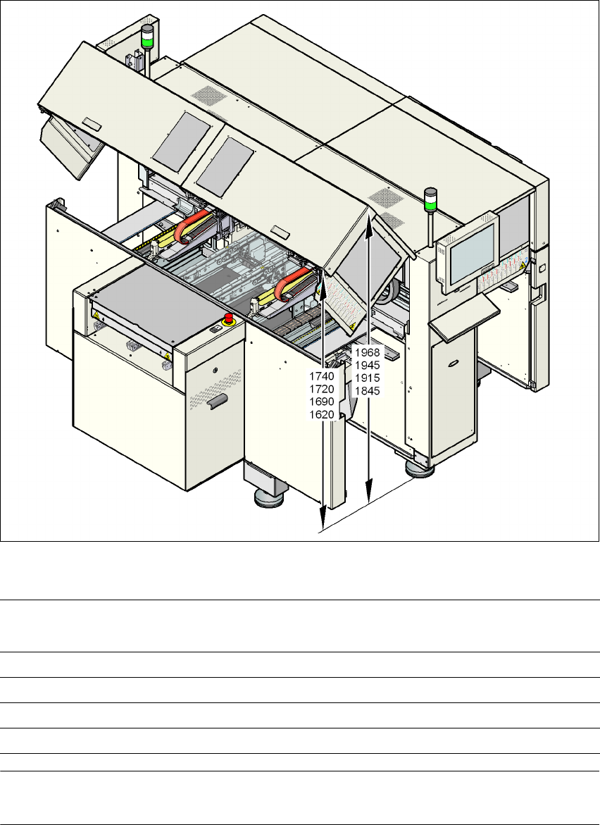
3.3.3 Height of the folded up protective cover
3
Fig. 3.3 - 2 Height of the folded-up protective cover - dimensions in millimeters
3
PLEASE NOTE 3
One can optionally increase the opening angle of the protective covers using other gas springs.
PCB conveyor height Height of bottom edge of the
lifted-up protective cover
Height of top edge of the lifted-
up protective cover
950 mm 1740 1968
930 mm 1720 1945
900 mm 1690 1915
830 mm 1620 1845
User manual SIPLACE D4i 3 Technical data for the machine
From software version SR.605.03 SP2 10/2012 EN edition 3.3 Dimensions and weight
93
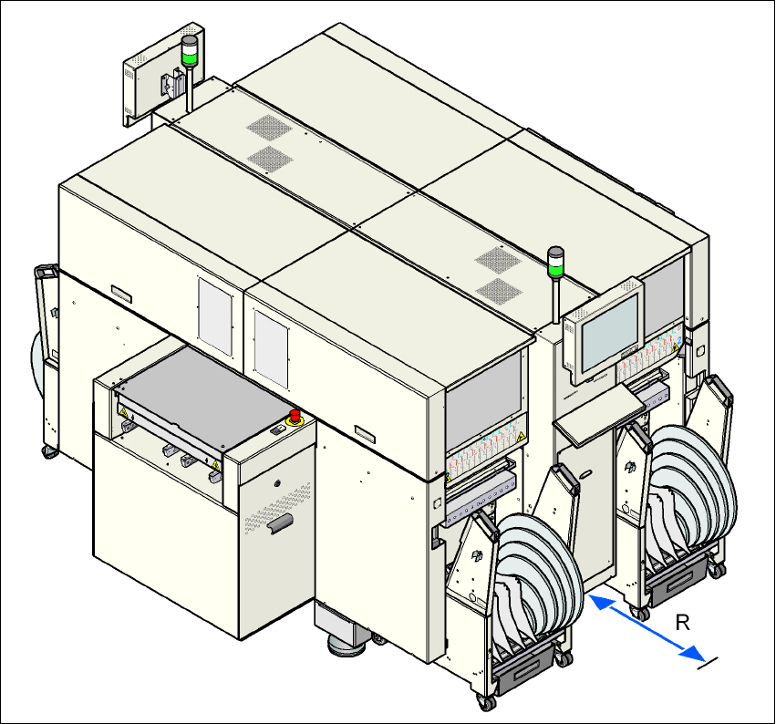
3.3.4 Maneuvering distance for the component trolley on the machine
3
Fig. 3.3 - 3 Maneuvering distance for the component trolley on the machine
The maneuvering distance R of the component trolley on the machine is 1200 mm.
3 Technical data for the machine User manual SIPLACE D4i
3.3 Dimensions and weight From software version SR.605.03 SP2 10/2012 EN edition
94
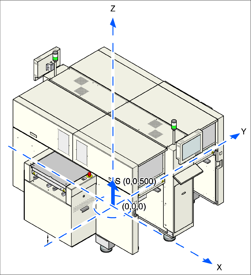
3.3.5 The machine’s center of gravity
3
Fig. 3.3 - 4 Machine's center of gravity in millimeters
X coordinate 0 mm
Y coordinate 0 mm
Z coordinate 500 mm high
These center of gravity coordinates relate to machines with a PCB conveyor height of 830 mm.