00198788-01_UM_SSI_DE_EN.pdf - 第32页
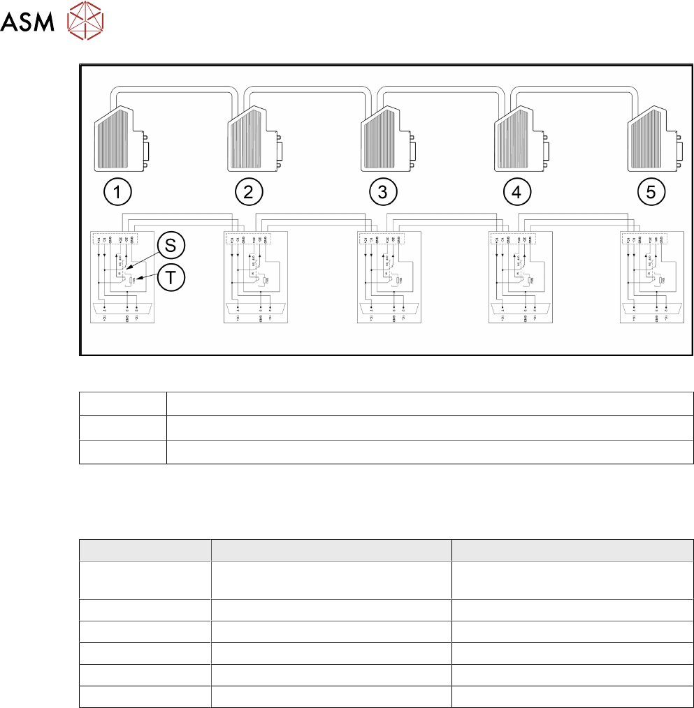
6 Übersichten 6.3 Ersatzteile 32 User Manual / Bedienungsanleitung SIPLACE Single Slot Interface 05/2021 Abb.5: CAN-Bus-Kabel Schaltplan 1 - 5 Stecker 1 bis 5 am Buskabel S Schiebeschalter am Stecker T Abschlusswidersta…
6 Übersichten
6.1 Blockdiagramm von Netzteil und EDIF
User Manual / Bedienungsanleitung SIPLACE Single Slot Interface 05/2021 31
6 Übersichten
6.1 Blockdiagramm von Netzteil und EDIF
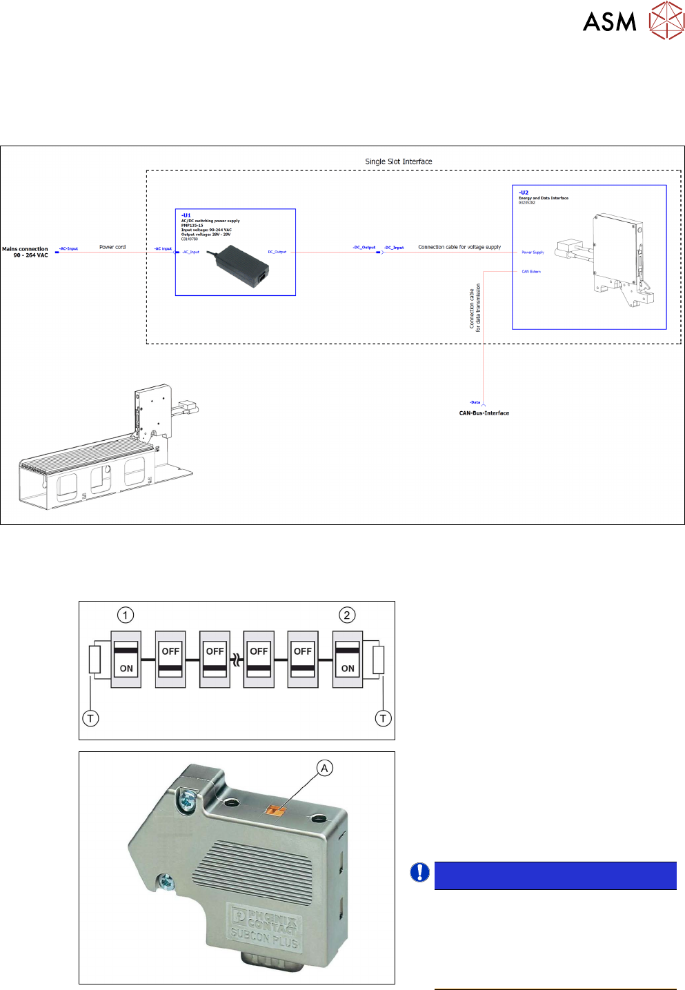
Abb.4: Blockdiagramm Netzteil und EDIF
6.2 CAN-Bus Kabel, Dockingstation, Abschlusswiderstand
Am Anfang (1) und am Ende (2) des Bus-
systems werden die Abschlusswiderstände
(T)
aktiviert. Gleichzeitig werden die An-
schlussklemmen (2C+/2C-) für das weiter-
führende Buskabel abgeschaltet.
► Schieben Sie am SUB-D-Stecker am
Anfang des Bussystems den Schie-
beschalter (A)
auf ON.
► Schieben Sie am SUB-D-Stecker am
Ende des Bussystems den Schie-
beschalter (A)
auf ON.
HINWEIS!
An allen anderen Knotenpunkten
des Bussystems muss der Ab-
schlusswiderstand deaktiviert sein!
Die Schiebeschalter der betref-
fenden SUB-D-Stecker müssen auf
OFF stehen.
.
6 Übersichten
6.3 Ersatzteile
32 User Manual / Bedienungsanleitung SIPLACE Single Slot Interface 05/2021
Abb.5: CAN-Bus-Kabel Schaltplan
1 - 5 Stecker 1 bis 5 am Buskabel
S Schiebeschalter am Stecker
T Abschlusswiderstand am Stecker
6.3 Ersatzteile
Folgende Ersatzteile sind für das SSI erhältlich:
Artikelnummer Bezeichnung deutsch Bezeichnung englisch
03149780-xx Power supply 90-264VAC 135W 29V
4,8A kpl.
Power supply 90-264VAC 135W 29V
4,8A cpl.
03127274-xx PCBA Single Slot EDIF 2 * PCBA Single Slot EDIF 2
03110865-xx PCBA Single Slot EDIF IrDA-Board II PCBA Single Slot EDIF IrDA board II
03042155-xx Energie-Dateninterface kpl. SSI Energy data interface compl. SSI
03048718-xx Kabel für SSI Power Cable for SSI power
03048719-xx Kabel für SSI Daten Cable for SSI data
* FBG = Flach Bau Gruppe = Platine, elektrische Schaltung (englisch = PCB = Printed Circuit
B
oard)

33User Manual / Bedienungsanleitung SIPLACE Single Slot Interface 05/2021
List of contents
List of contents
1 Introduction.. 35
1.1 Module Description.. 35
1.1.1 Typeplate and Serial Number.. 35
1.1.2 Technical Data.. 35
1.1.3 EU Declaration of Conformity.. 36
1.1.4 Correct Usage.. 36
1.1.5 Incorrect Usage.. 36
1.1.6 Environmentally-friendly disposal of materials and components.. 37
1.1.7 Electromagnetic compatibility (EMC).. 37
1.1.8 Use of original accessories and spare parts.. 37
1.2 Important Notes about this Manual.. 37
1.2.1 Contents and Filing of this Manual.. 37
1.2.2 Danger notes.. 37
1.2.3 Manufacturer's/supplier's liability.. 37
1.2.4 Release History.. 38
1.2.5 Further Information.. 38
1.2.5.1 How To Get Information.. 38
1.2.5.2 SIPLACE on the World Wide Web (WWW).. 38
2 Operational safety.. 39
2.1 Safety Instructions.. 39
2.1.1 Conventions for the use of safety instructions and symbols.. 39
2.1.2 Staff Qualifications and Training.. 39
2.1.3 Important notes on operational safety.. 40
2.1.3.1 General.. 40
2.1.3.2 Safety of Operators and Other Persons.. 40
2.1.3.3 Safety of Plant and Equipment.. 40
3 Function description and structure.. 41
3.1 Function description.. 41
3.2 Structure.. 42
3.3 Repairing the X Feeder Modules.. 43
4 Operation.. 45
4.1 Setting up the SSI.. 45
4.2 Connecting a Feeder Module.. 46
4.3 Removing the feeder module.. 48
4.4 Table adapter.. 49
4.5 Preparation table.. 50
4.6 Tasks for Setup Center.. 51
5 CAN ID mode and presettings.. 53
5.1 CAN ID mode.. 53
5.2 Setting the CAN ID.. 53
5.3 Setting the baud rate.. 55