00198788-01_UM_SSI_DE_EN.pdf - 第44页
3 Function description and structure 3.3 Repairing the X Feeder Modules 44 User Manual / Bedienungsanleitung SIPLACE Single Slot Interface 05/2021
3 Function description and structure
3.3 Repairing the X Feeder Modules
User Manual / Bedienungsanleitung SIPLACE Single Slot Interface 05/2021 43
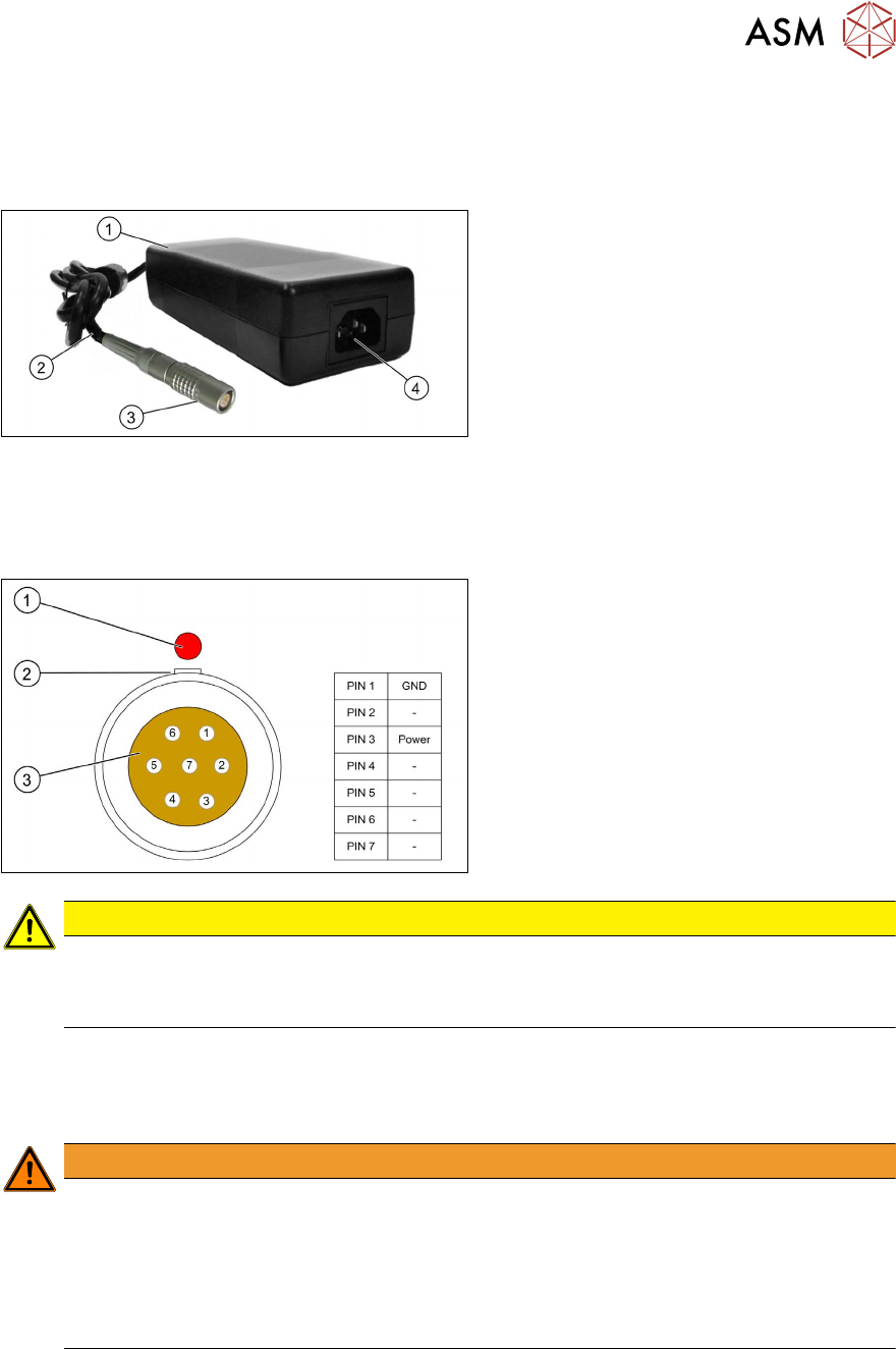
Power pack
To operate the SSI, the power pack supplied provides the required voltage of 29 V to a 7-pin Lemo
connector. The nominal voltage can be 90-264 VAC. The power pack automatically adjusts to the
incoming voltage.
The underside of the power pack is fitted
with Velcro tape to the inside of the steel
frame, so that the power on indicator (1)
is
visible.
The power pack cable (2) is run towards the
back in the steel frame and the Lemo con-
nector (3)
is connected to the SSI power
supply cable.
The connection plug (4) for the mains power
cable points towards the front of the steel
frame. The delivery package includes a Ger-
man mains cable and a US version mains
cable. Use the mains cable suitable for your
mains connection, to connect the SSI to the
power supply.
Connector on power pack cable:
(1) Red dot on the connector (identifying
mark)
(2) Groove (reverse polarity protection)
(3) Contacts (see table for assignment)
CAUTION
Operational safety
The power pack is electrically designed so that the SSI can be safely supplied with voltage.
► Only operate the SSI with this power pack.
3.3 Repairing the X Feeder Modules
If operating the feeder module when it is open with the SSI, observe the following:
WARNING
Observe the ESD regulations
Observe ESD safety regulations for the feeder modules:
► Before you open the side cover, make sure you are wearing the ESD protection wrist-
band, to prevent damage to the highly sensitive boards inside the feeder module.
► When working with the open feeder module, always use suitable ESD protection.
(ESD support, workplace, wristband)
There are no hazardous voltages in the feeder module itself. The cable and control boards only use
up to a maximum of 42 V (low voltage threshold).
Information about repairing the X feeder modules.
For more information about repairing the X feeder modules, refer to the service manual for the X
feeder modules.

3 Function description and structure
3.3 Repairing the X Feeder Modules
44 User Manual / Bedienungsanleitung SIPLACE Single Slot Interface 05/2021
4 Operation
4.1 Setting up the SSI
User Manual / Bedienungsanleitung SIPLACE Single Slot Interface 05/2021 45
4 Operation
4.1 Setting up the SSI
WARNING
Injury from falling parts
The assembly must be correctly placed on the table to prevent it falling down and causing
any injuries.
WARNING
Cables must be run correctly
If the cable is not run correctly, there is a general risk of the assembly getting caught on
parts or being pulled away.
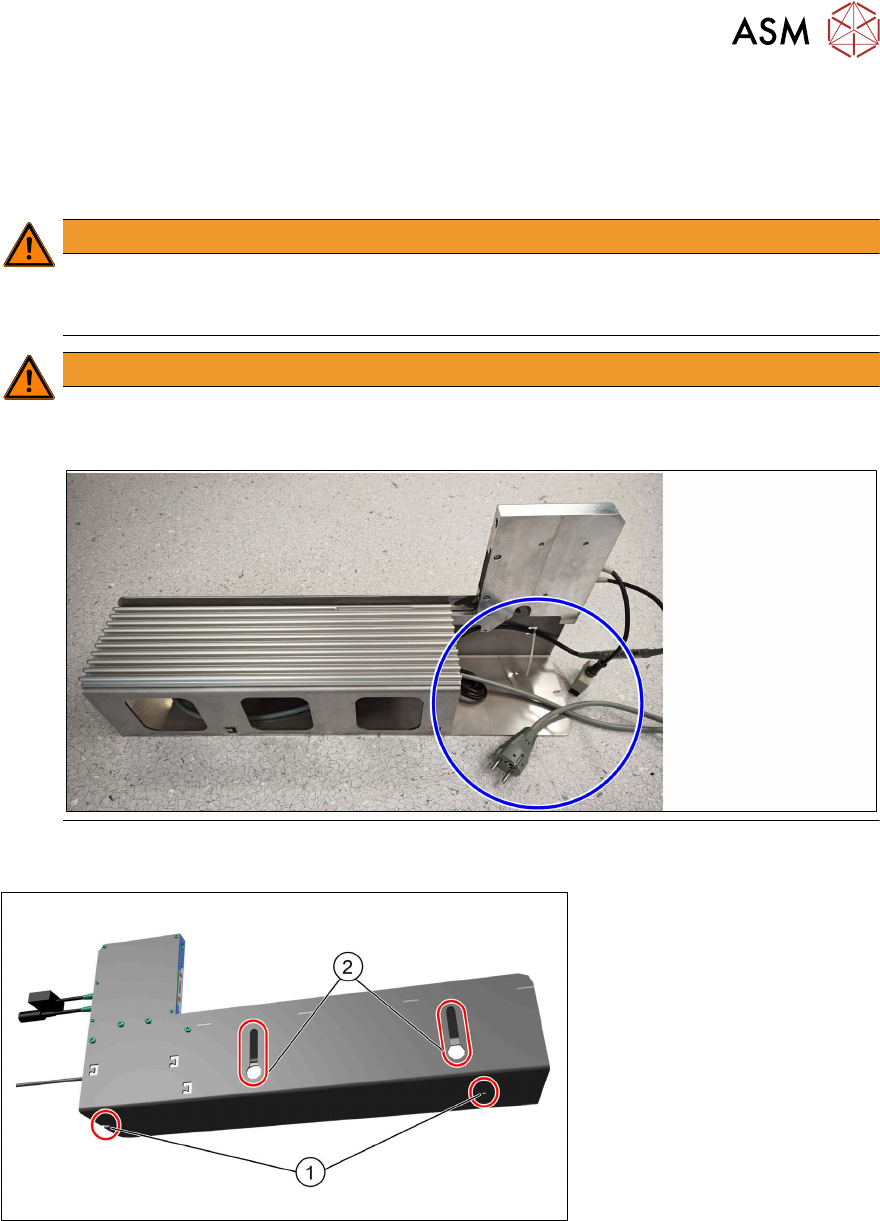
Before putting your SSI into operation, it should be placed on the table in a manner which protects
it from falling over or falling down. The SSI steel frame has the following attachment options:
●
2 holes (1) in the base plate of the steel frame for screwed attachment to the table adapter
(00120672-xx TableAdapter SingleSlotEnergy Interface)
●
2 hook-up slots (2) on the left side of the steel frame for side fixture to the preparation table
(00120670-xx Preparation table feeder modules typeX)