00198788-01_UM_SSI_DE_EN.pdf - 第46页
4 Operation 4.2 Connecting a Feeder Module 46 User Manual / Bedienungsanleitung SIPLACE Single Slot Interface 05/2021 Connecting the SSI to the power supply ► Connect the SSI power supply cable to the power pack cable. M…
4 Operation
4.1 Setting up the SSI
User Manual / Bedienungsanleitung SIPLACE Single Slot Interface 05/2021 45
4 Operation
4.1 Setting up the SSI
WARNING
Injury from falling parts
The assembly must be correctly placed on the table to prevent it falling down and causing
any injuries.
WARNING
Cables must be run correctly
If the cable is not run correctly, there is a general risk of the assembly getting caught on
parts or being pulled away.
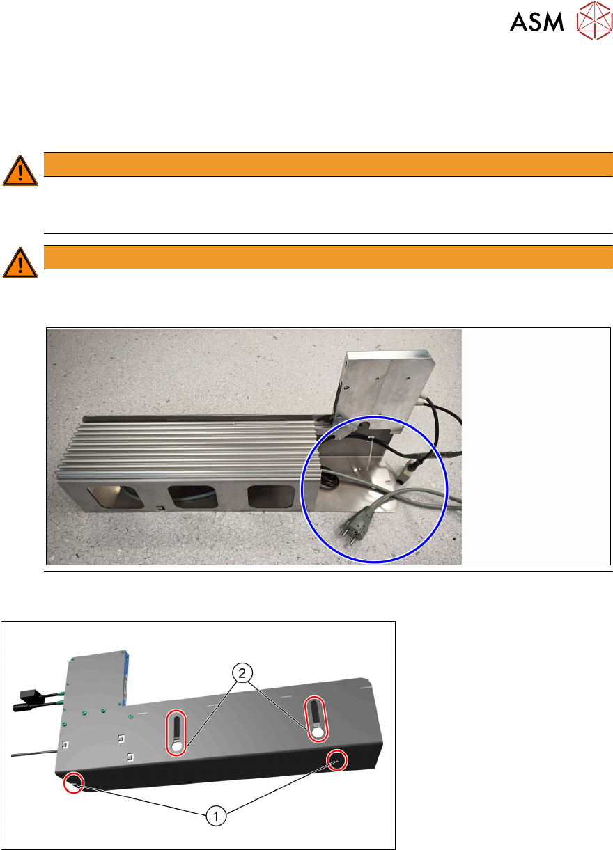
Before putting your SSI into operation, it should be placed on the table in a manner which protects
it from falling over or falling down. The SSI steel frame has the following attachment options:
●
2 holes (1) in the base plate of the steel frame for screwed attachment to the table adapter
(00120672-xx TableAdapter SingleSlotEnergy Interface)
●
2 hook-up slots (2) on the left side of the steel frame for side fixture to the preparation table
(00120670-xx Preparation table feeder modules typeX)
4 Operation
4.2 Connecting a Feeder Module
46 User Manual / Bedienungsanleitung SIPLACE Single Slot Interface 05/2021
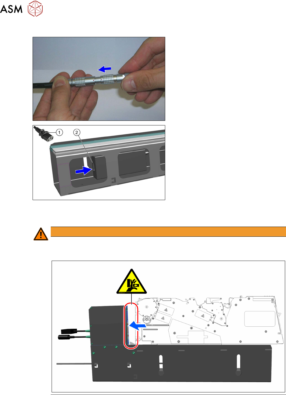
Connecting the SSI to the power supply
► Connect the SSI power supply cable to
the power pack cable. Make sure that
the red dot on both plugs is at the top.
► Use the mains cable suitable for your
mains connection.
► Insert the cool-device coupling for the
power pack (1)
into the connection (2)
on the power pack.
► Connect the power supply plug to an
appropriately grounded socket.
4.2 Connecting a Feeder Module
WARNING
Risk of body parts getting trapped/pinched when moving the feeder module in
Do not reach between the feeder module and the EDIF while the feeder module is moving
in. There is a risk of body parts getting trapped or pinched.
4 Operation
4.2 Connecting a Feeder Module
User Manual / Bedienungsanleitung SIPLACE Single Slot Interface 05/2021 47
WARNING
Risk of body parts being trapped at the locking latch
Do not reach into the swivel area of the locking latch while moving the feeder module in.
The locking latch moves independently up and then down again during the engage pro-
cess. There is a risk of body parts being trapped at the locking latch.
You do not need to disconnect the power pack from the mains power before connecting the feeder
module to the SSI.
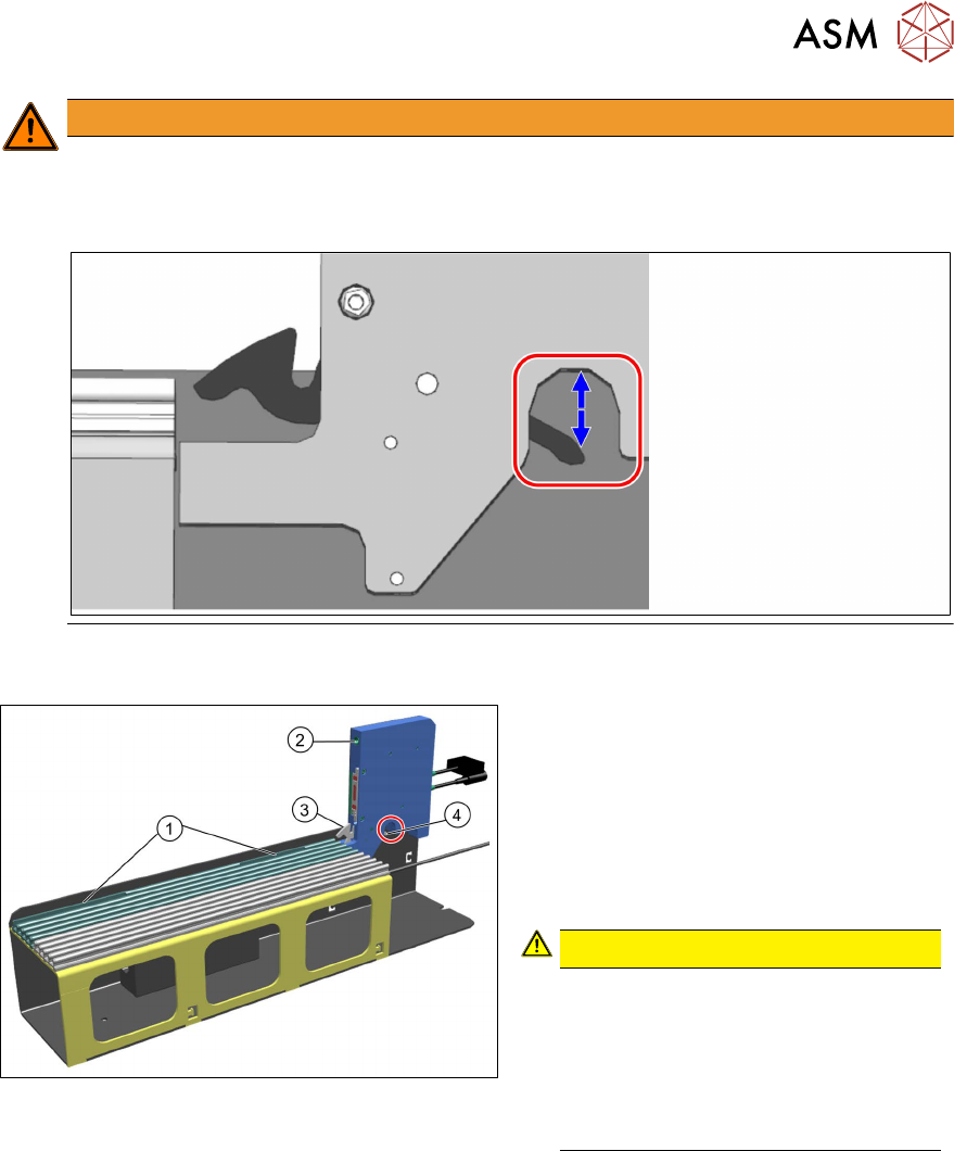
► Insert the feeder module to be checked
at the omega rail and make sure that
the feeder module engages with the re-
cesses in the omega profile (1
).
► Push the feeder module as far as the
stop and make sure that the guide pin
on the feeder module engages with the
drilled hole on the SSI (2)
.
CAUTION!
Make sure that you do not reach
into the swivel area of the locking
latch (4). The locking lever (3) snaps
into place independently and the
locking latch then moves up and
down again! There is a risk of body
parts being trapped.
.
► The locking lever (3) is pressed down
during this and will snap back again on
its own. This holds the feeder module
reliably in its position.