00198788-01_UM_SSI_DE_EN.pdf - 第48页
4 Operation 4.3 Removing the feeder module 48 User Manual / Bedienungsanleitung SIPLACE Single Slot Interface 05/2021 4.3 Removing the feeder module WARNING Risk of body parts being trapped at the locking latch To unlock…
4 Operation
4.2 Connecting a Feeder Module
User Manual / Bedienungsanleitung SIPLACE Single Slot Interface 05/2021 47
WARNING
Risk of body parts being trapped at the locking latch
Do not reach into the swivel area of the locking latch while moving the feeder module in.
The locking latch moves independently up and then down again during the engage pro-
cess. There is a risk of body parts being trapped at the locking latch.
You do not need to disconnect the power pack from the mains power before connecting the feeder
module to the SSI.
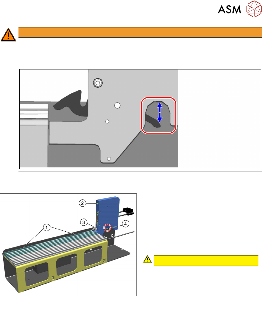
► Insert the feeder module to be checked
at the omega rail and make sure that
the feeder module engages with the re-
cesses in the omega profile (1
).
► Push the feeder module as far as the
stop and make sure that the guide pin
on the feeder module engages with the
drilled hole on the SSI (2)
.
CAUTION!
Make sure that you do not reach
into the swivel area of the locking
latch (4). The locking lever (3) snaps
into place independently and the
locking latch then moves up and
down again! There is a risk of body
parts being trapped.
.
► The locking lever (3) is pressed down
during this and will snap back again on
its own. This holds the feeder module
reliably in its position.
4 Operation
4.3 Removing the feeder module
48 User Manual / Bedienungsanleitung SIPLACE Single Slot Interface 05/2021
4.3 Removing the feeder module
WARNING
Risk of body parts being trapped at the locking latch
To unlock, only press against the locking latch from below. There is a risk of limbs being
trapped at the locking latch.
You need to disconnect the power pack from the mains power before disconnecting the feeder
module from the SSI.
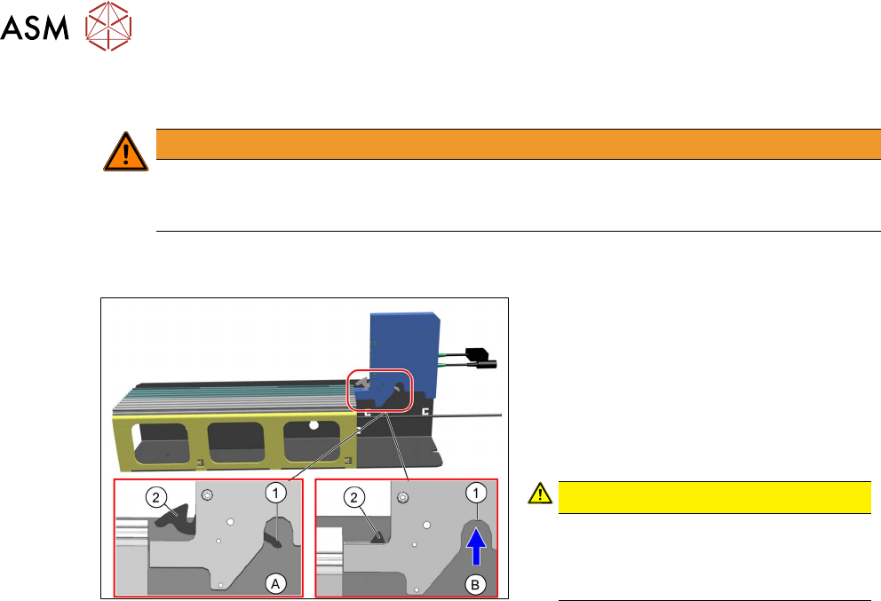
► Hold the feeder module in the SSI with
one hand.
The locking lever (2)
is still engaged
and the locking latch (1)
points down-
wards (A)
.
► With the other hand, press the locking
latch (1)
up and hold it in this position
(B)
.
CAUTION!
When pressing the locking latch (1)
up, only hold it on the underside.
There is otherwise a risk of limbs
being trapped.
.
► Pull the feeder module on the omega
rail back and out.
► Let go of the locking latch (1) as soon
as the locking lever (2)
is exposed.
4 Operation
4.4 Table adapter
User Manual / Bedienungsanleitung SIPLACE Single Slot Interface 05/2021 49
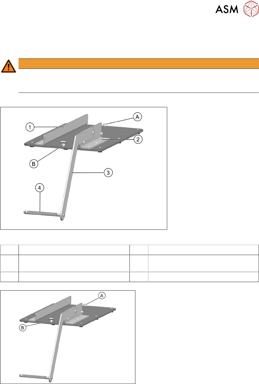
4.4 Table adapter
If you want to use the SSI for pre-setup, it can be fitted to a table adapter. This increases the stabil-
ity of the equipment and give the component reel a fixed place.
WARNING
Injury from falling parts
The assembly must be correctly placed on the table to prevent it falling down and causing
any injuries.
Sales number: 00120672-xx
Fig.2: SSI table adapter
1 Führungsprofil links 2 Guide profile, right
3 Reel arm 4 Axis for accommodating the component
reel
A Knurled screw, back B Knurled screw, front
Fasten the SSI to the table adapter:
► Loosen the back knurled screw (A) until
it is only slightly in the base plate.
► Loosen the front knurled screw (B)
completely.