OM-1352-003_w.pdf - 第21页
Contents Cont-2 Page Tg1357-ID-SO 6. Data ................................................................................................ 6-1 6.1 Pattern Program .........................................................…

Contents
Cont-1
Page
Tg1357-ID-SO
Before Use ............................................................................................. 1
About the Instruction Manual ................................................................. 2
Caution and Warning ............................................................................. 3
Limited Warranty .............................................................................. 3
About Specification Change ............................................................. 4
About Disposal of Machine .............................................................. 4
Safety Precautions
1. About Safety Precaution Labels ..................................................... Safe - 1
2. Common Precautionary Items ....................................................... Safe - 3
3. Alert Indications in Instruction Manual ........................................... Safe - 7
4. Alert Labels .................................................................................... Safe - 8
5. Precautionary Items for Correct Operations ................................... Safe -11
Contents .............................................................................................. Cont - 1
1. Scope ............................................................................................. 1-
1
1.1 About the Flux Dispensing Unit .............................................. 1-1
1.2 Specifications of Flux Dispensing Unit .................................... 1-1
1.3 Names and Functions of Each Section ................................... 1-4
1.4 Structure and Names .............................................................. 1-6
1.5 Outline of Actions .................................................................... 1-7
2. Placement Action Mode ................................................................. 2-1
2.1 Normal Operation (Dip Transfer 1) ......................................... 2-1
2.2 Bump Ball Missing Confirmation after
Flux Dispensing (Dip Transfer 2) ......................... 2-2
2.3 Recognition of Bottom Component
Land before Placement (Dip Transfer 3) ............. 2-4
3. Handling of Flux Dispensing Unit ................................................... 3-1
3.1 Installation Procedure for Flux Dispensing Unit ...................... 3-2
3.2 Uninstallation Procedure for Flux Dispensing Unit ................. 3-3
3.3 Procedure for Syringe Replacement ....................................... 3-4
4. Flux Dispensing Unit Setup Procedure .......................................... 4-1
5. Operation ....................................................................................... 5-1
5.1 "Operation" Menu ................................................................... 5-1
5.1.1 Selection of Operation Mode ......................................... 5-1
5.1.2 Selection of Test Mode .................................................. 5-3
5.2 Component Recognition Test .................................................. 5-4
0703-003

Contents
Cont-2
Page
Tg1357-ID-SO
6. Data ................................................................................................ 6-1
6.1 Pattern Program ..................................................................... 6-1
6.1.1 Placement Feeder Location Data .................................. 6-1
6.1.2 Setup for the Component Library
"Control Data" for Top Components .................... 6-6
6.2 Component Library ................................................................. 6-8
7. Offsets ............................................................................................ 7-1
8. Maintenance ................................................................................... 8-1
8.1 Precautionary Items before Maintenance ............................... 8-1
8.2 Preparation for Maintenance .................................................. 8-1
8.3 Maintenance Method .............................................................. 8-2
8.3.1 Understanding of
Maintenance Items on Each Section ................... 8-2
8.3.2 Daily Maintenance ......................................................... 8-3
8.4 List of Servicing Parts ............................................................. 8-5
9. Troubleshooting .............................................................................. 9-1
9.1 Starting Guidance ................................................................... 9-1
9.2 Error IDs and Remedial Procedures ....................................... 9-1
9.2.1 Others ............................................................................ 9-1
9.2.2 Automatic Operation Error ............................................. 9-1
10. Material .......................................................................................... 10-1
10.1 Electrical Circuit Diagrams ...................................................... 10-1
10.2 I/O Check Table of Drawer Connector Pins ............................ 10-2
10.3 Relation between Flux Forming Film Thickness
and Specified Values for Squeegee ........... 10-3
Accompanying Material ........................................................................ A
Material Safety Data Sheet
Deltalux 529D (Senju Industry Co., Ltd.)
0703-003
1-1
Tg1357-ID-SO
1. Scope
0703-003
1. Scope
1.1 About the Flux Dispensing Unit
The flux dispensing unit is installed on the main machine (GXH Series)
and is used to so control the supplied flux so that the thickness of the flux
becomes the specified one, for POP component placement.
Also, it detects flux remaining on the rotating disk and automatically supplies
Flux.
1.2 Specifications of Flux Dispensing Unit
Table 1-1
Item Description
1. Outline of Actions
•
Flux is dispensed on the rotational disk and the thick film is flattened
evenly by the squeegee whose height is adjusted to the specified one.
•
The rotating disk is stopped just before flux dispense and a flux transfer
operation is performed.
2. Applicable Head Multifunctional Head: HM-G100 (Option)
Note:
A multifunction head is required because the outline detection (back
lighting recognition) is adopted and a spring nozzle is used.
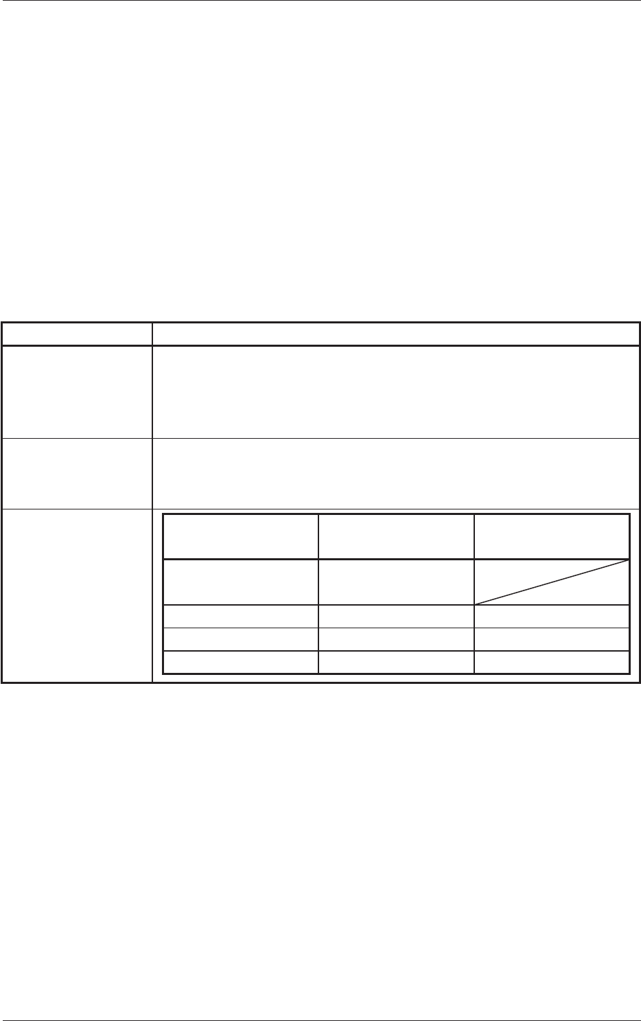
3. Applicable
Components
Compnent
Recognition Camera
Standard
High Resolution
Camera (Option)
Dimensions Max. 17.5
×
17.5
Min. 1.5
× 1.5
Bump Diameter Min. 0.3 mm Min. 0.13 mm
Bump Pich Min. 0.5 mm Min. 0.25 mm
Bump Ball Distance Min. 0.2 mm Min. 0.12 mm