OM-1352-003_w.pdf - 第23页
1-2 Tg1357-ID-SO 0703-003 T able 1-2 Item Description 4. Flux Adjustable Range of Thick Film : 0.02 to 0.3 mm Minimum Unit of Adjustment : 0.01 mm Adjustment of Thick Film : Manual Adjustment Ref.: Adjustment with a Spac…
1-1
Tg1357-ID-SO
1. Scope
0703-003
1. Scope
1.1 About the Flux Dispensing Unit
The flux dispensing unit is installed on the main machine (GXH Series)
and is used to so control the supplied flux so that the thickness of the flux
becomes the specified one, for POP component placement.
Also, it detects flux remaining on the rotating disk and automatically supplies
Flux.
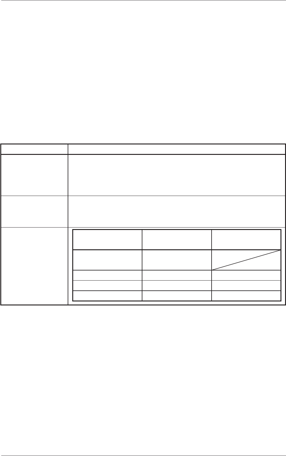
1.2 Specifications of Flux Dispensing Unit
Table 1-1
Item Description
1. Outline of Actions
•
Flux is dispensed on the rotational disk and the thick film is flattened
evenly by the squeegee whose height is adjusted to the specified one.
•
The rotating disk is stopped just before flux dispense and a flux transfer
operation is performed.
2. Applicable Head Multifunctional Head: HM-G100 (Option)
Note:
A multifunction head is required because the outline detection (back
lighting recognition) is adopted and a spring nozzle is used.
3. Applicable
Components
Compnent
Recognition Camera
Standard
High Resolution
Camera (Option)
Dimensions Max. 17.5
×
17.5
Min. 1.5
× 1.5
Bump Diameter Min. 0.3 mm Min. 0.13 mm
Bump Pich Min. 0.5 mm Min. 0.25 mm
Bump Ball Distance Min. 0.2 mm Min. 0.12 mm

1-2
Tg1357-ID-SO
0703-003
Table 1-2
Item Description
4. Flux Adjustable Range of Thick Film : 0.02 to 0.3 mm
Minimum Unit of Adjustment : 0.01 mm
Adjustment of Thick Film : Manual Adjustment
Ref.:Adjustment with a Spacer Block or
Micrometer
Supply Method : Manual Supply
Ref.:Detection of Remaining Flux and
Flux Supply from External Syringe
Range of Viscosity : 10 to 20 Pa/s
(Required Ambient Temperature:25 ± 5°C)
1.2 Specifications of Flux Dispensing Unit

1-3
Tg1357-ID-SO
0703-003
Table 1-3
Item Description
5. Placement
Seguence Tact
Operating Pattern 1 (Normal Operation)
Pickup
→
Recognition (Outline, Bump)
→
Flux Dispense
→
Recognition (Outline)
→
Placement
1.6 seconds
Operating Pattern 2
(Confirmation of Missing Bump Balls after Flux Dispense)
Pickup
→
Recognition (Bump)
→
Flux Dispense
→
Recognition (Bump)
→
Placement
Note:
Bump Diameter:
φ
0.4 mm or more
Applicable Components:
Components whose bump balls can be recognized after
flux dispense
1.8 seconds
Operation Pattern 3 (Recognition of Component Lands
on Botton before Placement)
The component lands on the botton of PCB are recognized
before placement operations described above in "Operating
Pattern 1" and "Operating Pattern 2"
Note:
(a) The placement coordinates X and Y of the
components are determined based on the lands of
the components on the bottom.
(b) Applicable Components on Bottom:
Thickness 1.5 mm or less
2.1 seconds
Note:
No deceleration is made in the tact speed when a head places one
component.
Others
Impact Reduced by Secondary Descending Deceleration Operation
6. Unit Location The unit is mounted on the feeder base.
Note: The unit can also be mounted on the base (4-lane space) beside the
JEDEC Mult-Layer Tray Feeder with Additional Side Feeder.
7. Number of
Available Lanes
5 Lanes
8. Setting of
Rotational Speed
Manual Setting with Variable Resistor
Ref.: Rotational Speed Control for Flux Thick Film Adjustment
9. Power Supply 24 V DC (40 W) is supplied from the main machine (GXH Series).
Ref.:The power is supplied through the drawer connector of the feeder base.
10. Maintenance-
ability
•
The unit can be connected to Tape Feeder Power Unit:
G-S006-02 (option) and operated independently for maintenance.
•
The rotational disk is detachable.
1.2 Specifications of Flux Dispensing Unit