OM-1352-003_w.pdf - 第25页
1-4 Tg1357-ID-SO 0703-003 T able 1-3 Item Description 1 1. Dustproof Measures A transparent cover can be installed on the flux supply position. 12. Component Loading System Multi-Layer T ray Feeder (FP-G100), Shuttle Feed…
1-3
Tg1357-ID-SO
0703-003
Table 1-3
Item Description
5. Placement
Seguence Tact
Operating Pattern 1 (Normal Operation)
Pickup
→
Recognition (Outline, Bump)
→
Flux Dispense
→
Recognition (Outline)
→
Placement
1.6 seconds
Operating Pattern 2
(Confirmation of Missing Bump Balls after Flux Dispense)
Pickup
→
Recognition (Bump)
→
Flux Dispense
→
Recognition (Bump)
→
Placement
Note:
Bump Diameter:
φ
0.4 mm or more
Applicable Components:
Components whose bump balls can be recognized after
flux dispense
1.8 seconds
Operation Pattern 3 (Recognition of Component Lands
on Botton before Placement)
The component lands on the botton of PCB are recognized
before placement operations described above in "Operating
Pattern 1" and "Operating Pattern 2"
Note:
(a) The placement coordinates X and Y of the
components are determined based on the lands of
the components on the bottom.
(b) Applicable Components on Bottom:
Thickness 1.5 mm or less
2.1 seconds
Note:
No deceleration is made in the tact speed when a head places one
component.
Others
Impact Reduced by Secondary Descending Deceleration Operation
6. Unit Location The unit is mounted on the feeder base.
Note: The unit can also be mounted on the base (4-lane space) beside the
JEDEC Mult-Layer Tray Feeder with Additional Side Feeder.
7. Number of
Available Lanes
5 Lanes
8. Setting of
Rotational Speed
Manual Setting with Variable Resistor
Ref.: Rotational Speed Control for Flux Thick Film Adjustment
9. Power Supply 24 V DC (40 W) is supplied from the main machine (GXH Series).
Ref.:The power is supplied through the drawer connector of the feeder base.
10. Maintenance-
ability
•
The unit can be connected to Tape Feeder Power Unit:
G-S006-02 (option) and operated independently for maintenance.
•
The rotational disk is detachable.
1.2 Specifications of Flux Dispensing Unit

1-4
Tg1357-ID-SO
0703-003
Table 1-3
Item Description
11. Dustproof
Measures
A transparent cover can be installed on the flux supply position.
12. Component
Loading System
Multi-Layer Tray Feeder (FP-G100),
Shuttle Feeder (FP-G300), and Tape Feeder (GT-****)
Note: The handling component size shall condorm to the tray specifications.
13. I/O Interfaces HLS and serial communications systems are used for the I/O interfaces.
Ref.: Through Drawer Connector of Feeder Base
14. Dimensions
Main Unit : Approx. 84 mm (Width) × 548 mm (Depth) × 165 mm (Height)
Attachment : Approx. 76 mm (Width) × 282 mm (Depth) × 128 mm (Height)
15. Mass Approx. 7.5 kg
16. Others
•
A spring nozzle ZX28 (option) is separately required.
1.2 Specifications of Flux Dispensing Unit
1-5
Tg1357-ID-SO
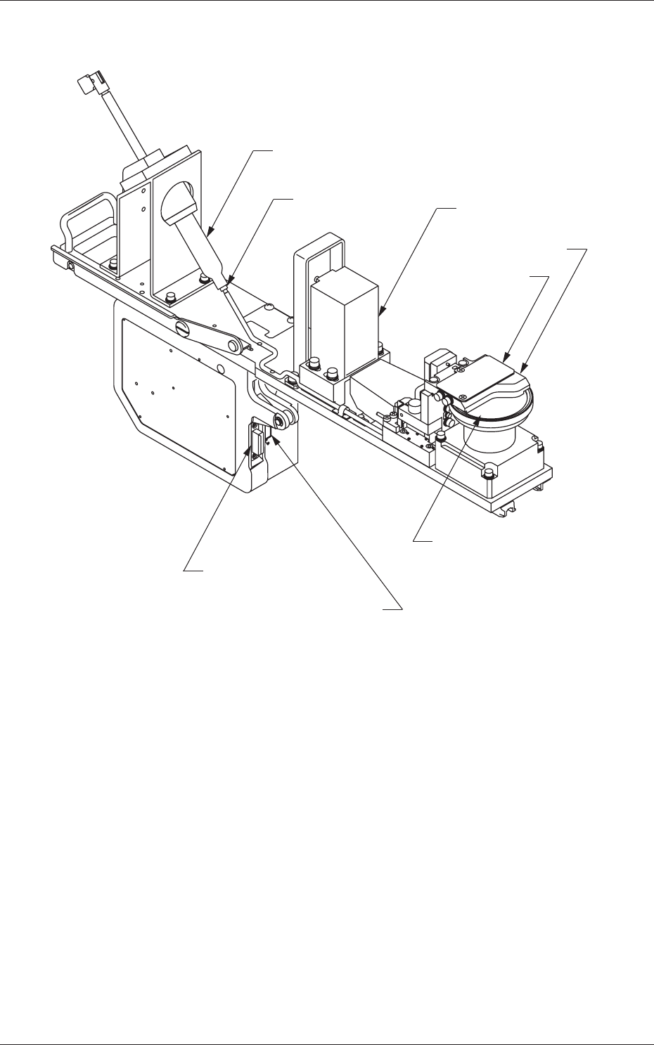
1.3 Names and Functions of Each Section
[5] Syringe
[6] Needle
[4] Motor
[3]
Transparent
Cover
[2] Squeegee
[1] Drum (Rotational Disk)
[7] Drawer Connector 1
[8] Drawer Connector 2
Fig.1
[1] Drum (Rotational Disk)
From this position flux is dispensed.
[2] Squeegee
It makes for an even flux coating thickness.
[3] Transparent Cover
It is a transparent cover for dustproofing.
0703-003
1.3 Names and Functions of Each Section