OM-1352-003_w.pdf - 第32页
2-3 Tg1357-ID-SO This function confirms that, certainly , the flux has been applied to all bumps after the flux application. When the flux has been applied, the bump diameter normally looks larger in the recognition processi…
2-2
Tg1357-ID-SO
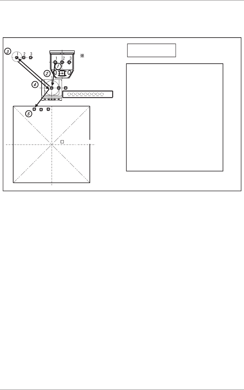
2.2 Bump Ball Missing Confirmation after Flux Dispensing
(Dip Transfer 2)
Transfer Position
Component Picks
with Nozzle #1
Multi Functional Head
Component Recognition Camera
Nozzle Stocker (Housing)
(Step 1) Pickup → (Step 2) Recognition (Bump) →
(Step 3) Flux Application →
(Step 4) Recognition (Bump) → (Step 5) Placement
Note: When the recognition is performed (step 4),
the bump missing check and flux application
check (if the flux is applied on the bump) are
performed.
For the XY placement position (where the
bump is limited to recognizable components,
after the flux application) the component is
placed by using the PEC recognition mark as
the reference.
The position is estimated and the component
placed using the bump as the reference.
PCB (460 × 460)PCB (460 × 460)
<Dip Transfer 2>
Fig.6
0703-003
2.2 Bump Ball Missing Confirmation after Flux Dispensing (Dip Transfer 2)
2-3
Tg1357-ID-SO
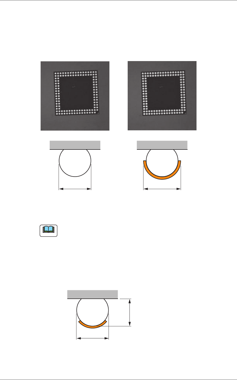
This function confirms that, certainly, the flux has been applied to all bumps
after the flux application.
When the flux has been applied, the bump diameter normally looks larger in
the recognition processing. By means of measuring the bump diameters and
comparing them before and after the flux application you are able to ensure
whether or not the flux has been judged.
D D +
a
Before Application After Application
Fig.7
Note
(a) This function is applicable to the bump diameter of
φ
0.4mm or more.
(b) If the flux coating thickness is too thin for the bump thickness, the
following figure shows the resultant difference as too small in the
measuring of bump diameter before and after the flux application.
If the flux coating thickness is too thick and the flux is attached to the
mold, the bump diameter can not be accurately measured.
This function should be used to secure a coating thickness of about
60% of bump thickness.
D
Before Application
Bump Thickness
Fig.8
0703-003
2.2 Bump Ball Missing Confirmation after Flux Dispensing (Dip Transfer 2)
2-4
Tg1357-ID-SO
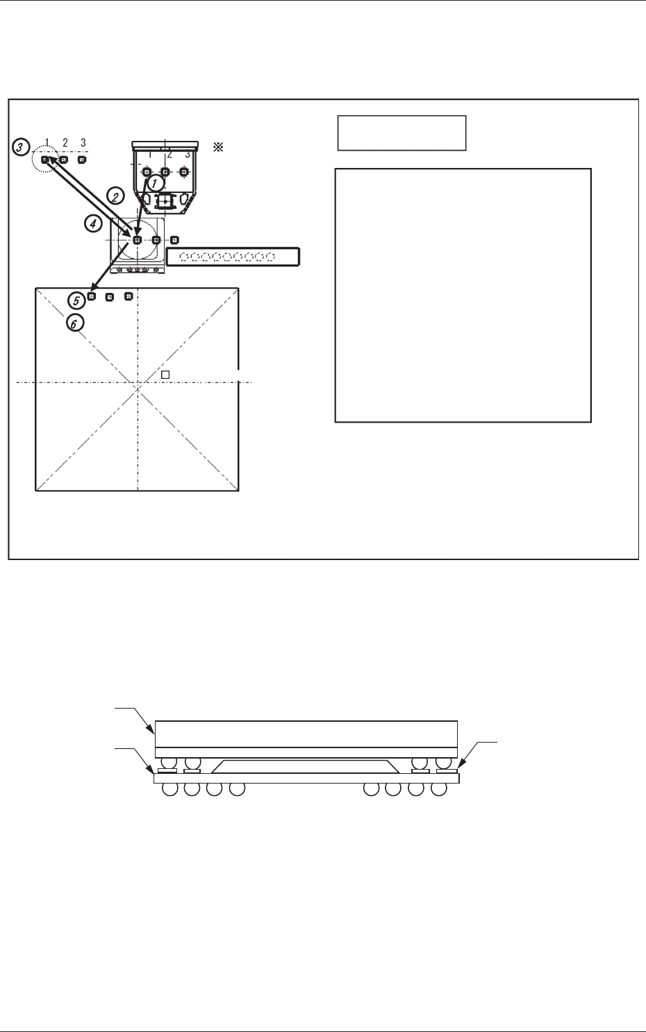
2.3 Recognition of Bottom Component Land before
Placement (Dip Transfer 3)
Transfer Position
Component Picks
with Nozzle #1
Multi Functional Head
Component Recognition Camera
Nozzle Stocker (Housing)
<Dip Transfer 1> + Recognition of Bottom
Component Land before Placement
(Step 1) Pickup → (Step 2) Recognition (Outline and
Bump) → (Step 3) Flux Application →
(Step 4) Recognition (Outline) →
(Step 5) Land Recognition → (Step 6) Placement
<Dip Transfer 2> + Recognition of Bottom
Component Land before Placement
(Step 1) Pickup → (Step 2) Recognition (Bump)
→ (Step 3) Flux Application →
(Step 4) Recognition (Bump) →
(Step 5) Land Recognition → (Step 6) Placement
PCB (460 × 460)PCB (460 × 460)
<Dip Transfer 3>
Fig.9
In the POP component placement, this function recognizes the land on the
upper surface of the bottom component, and finds the placement position for
the bottom component, and then places the top component.
Land on the upper
surface of
the bottom component
Top Component
Bottom
Component
Fig.10
0703-003
2.3 Recognition of Bottom Component Land before Placement (Dip Transfer 3)