OM-1352-003_w.pdf - 第34页
3-1 Tg1357-ID-SO 0703-003 3. Handling of Flux Dispensing Unit Notice Before installing a flux dispensing unit on the bank feeder change cart, note the following. • Lock the caster brakes (2 places) of the bank feeder chan…
2-4
Tg1357-ID-SO
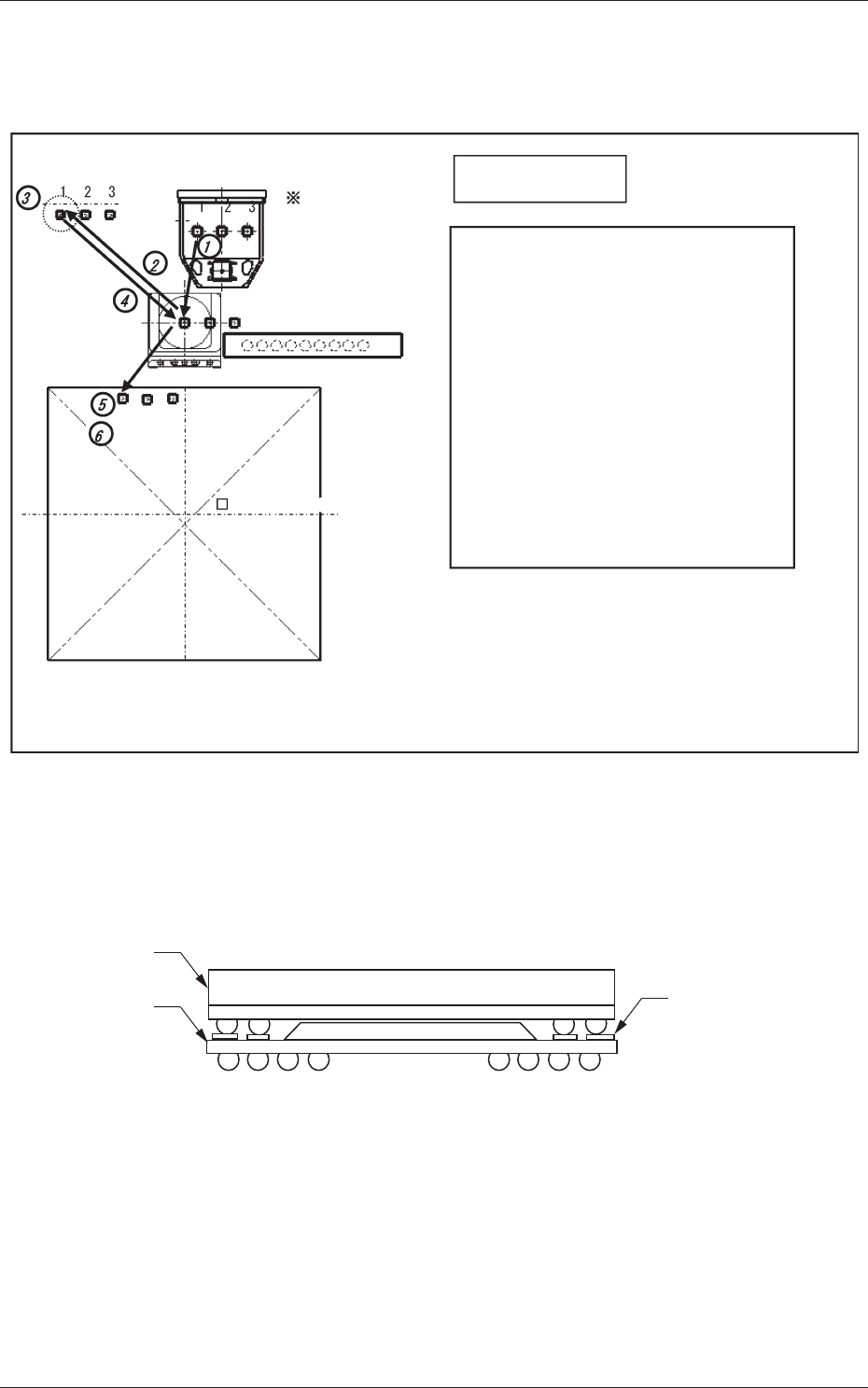
2.3 Recognition of Bottom Component Land before
Placement (Dip Transfer 3)
Transfer Position
Component Picks
with Nozzle #1
Multi Functional Head
Component Recognition Camera
Nozzle Stocker (Housing)
<Dip Transfer 1> + Recognition of Bottom
Component Land before Placement
(Step 1) Pickup → (Step 2) Recognition (Outline and
Bump) → (Step 3) Flux Application →
(Step 4) Recognition (Outline) →
(Step 5) Land Recognition → (Step 6) Placement
<Dip Transfer 2> + Recognition of Bottom
Component Land before Placement
(Step 1) Pickup → (Step 2) Recognition (Bump)
→ (Step 3) Flux Application →
(Step 4) Recognition (Bump) →
(Step 5) Land Recognition → (Step 6) Placement
PCB (460 × 460)PCB (460 × 460)
<Dip Transfer 3>
Fig.9
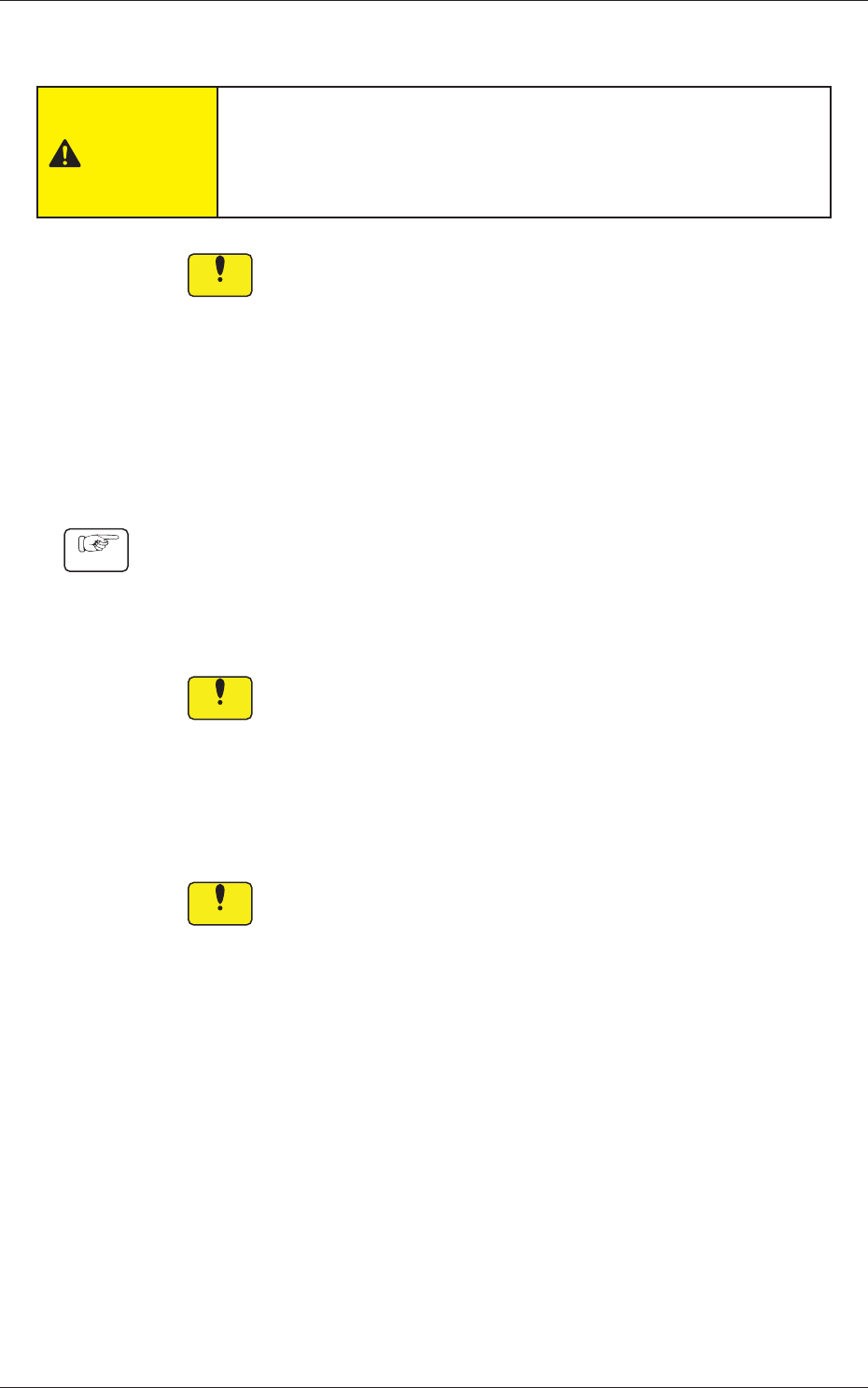
In the POP component placement, this function recognizes the land on the
upper surface of the bottom component, and finds the placement position for
the bottom component, and then places the top component.
Land on the upper
surface of
the bottom component
Top Component
Bottom
Component
Fig.10
0703-003
2.3 Recognition of Bottom Component Land before Placement (Dip Transfer 3)

3-1
Tg1357-ID-SO
0703-003
3. Handling of Flux Dispensing Unit
Notice
Before installing a flux dispensing unit on the bank feeder change
cart, note the following.
• Lock the caster brakes (2 places) of the bank feeder change cart.
• If the flux dispensing unit is seated afloat, vacuum nozzles or the
machine (GXH Series) will be damaged, causing pickup errors.
Be sure to install the flux dispensing unit correctly.
CAUTION
•
Be sure to hold the handle to move the bank feeder change cart.
•
While attaching the handle slides, be sure to prevent your
fingers from getting jammed.
•
Be careful not to hit your foot against the cart while moving the
bank feeder change cart.
•
Try to wear a pair of shoes that can protect your toes and have
slip- and puncture-resistance soles (thickness: 10 mm or more)
while working.
3. Handling of Flux Dispensing Unit
3-2
Tg1357-ID-SO
0703-003
3.1 Installation Procedure for Flux Dispensing Unit
CAUTION
Do not drop any flux dispensing unit during the attachment or
detachment. Otherwise, a foot injury will result or some feeders may be
damaged.
Carefully handle each unit one by one and do not drop any.
Notice
(a) If the flux dispensing unit is seated afloat, the machine
(GXH Series) may be damaged or pickup errors will be
caused.
Be sure to install the unit correctly on the feeder base.
(b) Keep the unused flux dispensing unit uninstalled from the
bank feeder change cart.
If a flux dispensing unit is kept used for a long period of
time, the flux is hardened. Using such a unit will cause
defective components.
Procedure
(1) Before installing a flux dispensing unit, confirm that no foreign
substances (dirt or dust) are found on the feeder base located on the
upper area of the cart.
(2) Install the flux dispensing unit on the specified feeder No. position.
Notice
Do not select a wrong feeder No. position. Otherwise, some
components may be trapped in the drum (rotational disk) area.
(3) Grasp the grip and insert the end of the flux dispensing unit so that the
end can be aligned correctly with the rails of the feeder base.
At this time, ensure that the unit is securely installed by pushing the
rear side of the grip forward.
Notice
Be sure to install the flux dispensing unit securely on the rails
of the feeder base.
(4) Push the grip and slowly insert the unit forward until it makes a "click"
sound. At this time, confirm that the connectors of the flux dispensing
unit are securely connected.
3.1 Installation Procedure for Flux Dispensing Unit