OM-1352-003_w.pdf - 第39页
3-6 Tg1357-ID-SO 0703-003 (5) Set up the cylinder to be replaced and insert it into the needle. (6) Insert the pushing rod (with the fixing plate moved to the end) into the cylinder . Notice Be sure to confirm that the fixi…
3-5
Tg1357-ID-SO
0703-003
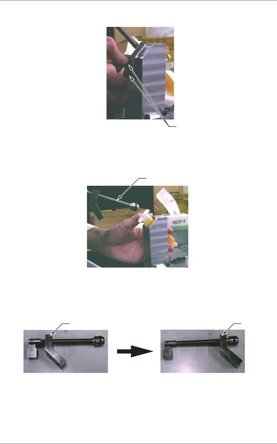
(2) Remove two screws fastening the cylinder.
Screws
Fig. 12
(3) Pull out the pushing rod from the cylinder.
Pushing Rod
Fig. 13
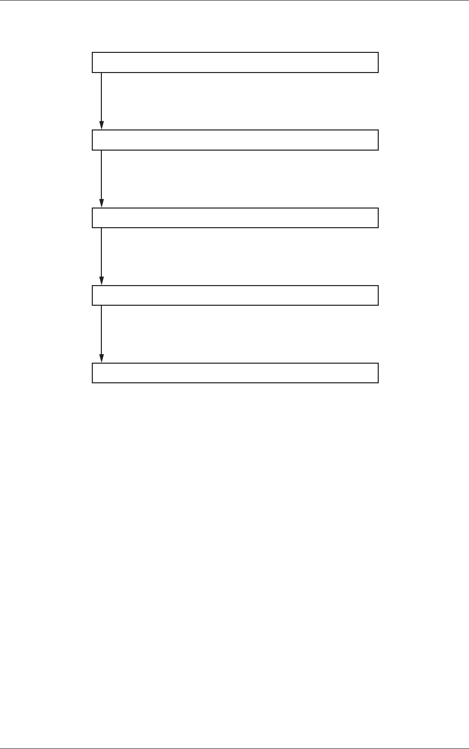
(4) Move the fixing plate of the detached pushing rod until it reaches
the end completely.
Fixing Plate Fixing Plate
Fixing Plate Location of
Detached Pushing Rod
Moved Fixing Plate Location
Fig. 13-1
3.3 Procedure for Syringe Replacement

3-6
Tg1357-ID-SO
0703-003
(5) Set up the cylinder to be replaced and insert it into the needle.
(6) Insert the pushing rod (with the fixing plate moved to the end)
into the cylinder.
Notice
Be sure to confirm that the fixing plate is completely
moved to the end before inserting the pushing rod.
If the fixing plate is not moved completely to the end
and the pushing rod is inserted, flux may leak out of
the cylinder.
(7) Tighten the two screws firmly to secure the fixing plate of the
pushing rod.
3.3 Procedure for Syringe Replacement
4-1
Tg1357-ID-SO
4. Flux Dispensing Unit Setup Procedure
Component Library Setting
Pattern Program Setting
Flux Applied Component Recognition Text
Automatic Operation
Operation Mode Setting
Set the component library.
Refer to "6.2 Component Library" for details.
Set the pattern program.
Refer to "6.1 Pattern Program" for details.
Confirm with the flux applied component recognition text.
Refer to "5.2 Flux Applied Component Recognition Test"
for details.
Set the operation mode.
Refer to "5.1 "Operation Mode" Menu" for details.
0703-003
4. Flux Dispensing Unit Setup Procedure