OM-1352-003_w.pdf - 第45页
5-4 Tg1357-ID-SO 0703-003 5.2 Component Recognition T est This window enables you check whether or not the component designated using a test ID can normally be recognized. When the [COMP RCG] button on the "DVC. TES…
5-3
Tg1357-ID-SO
0703-003
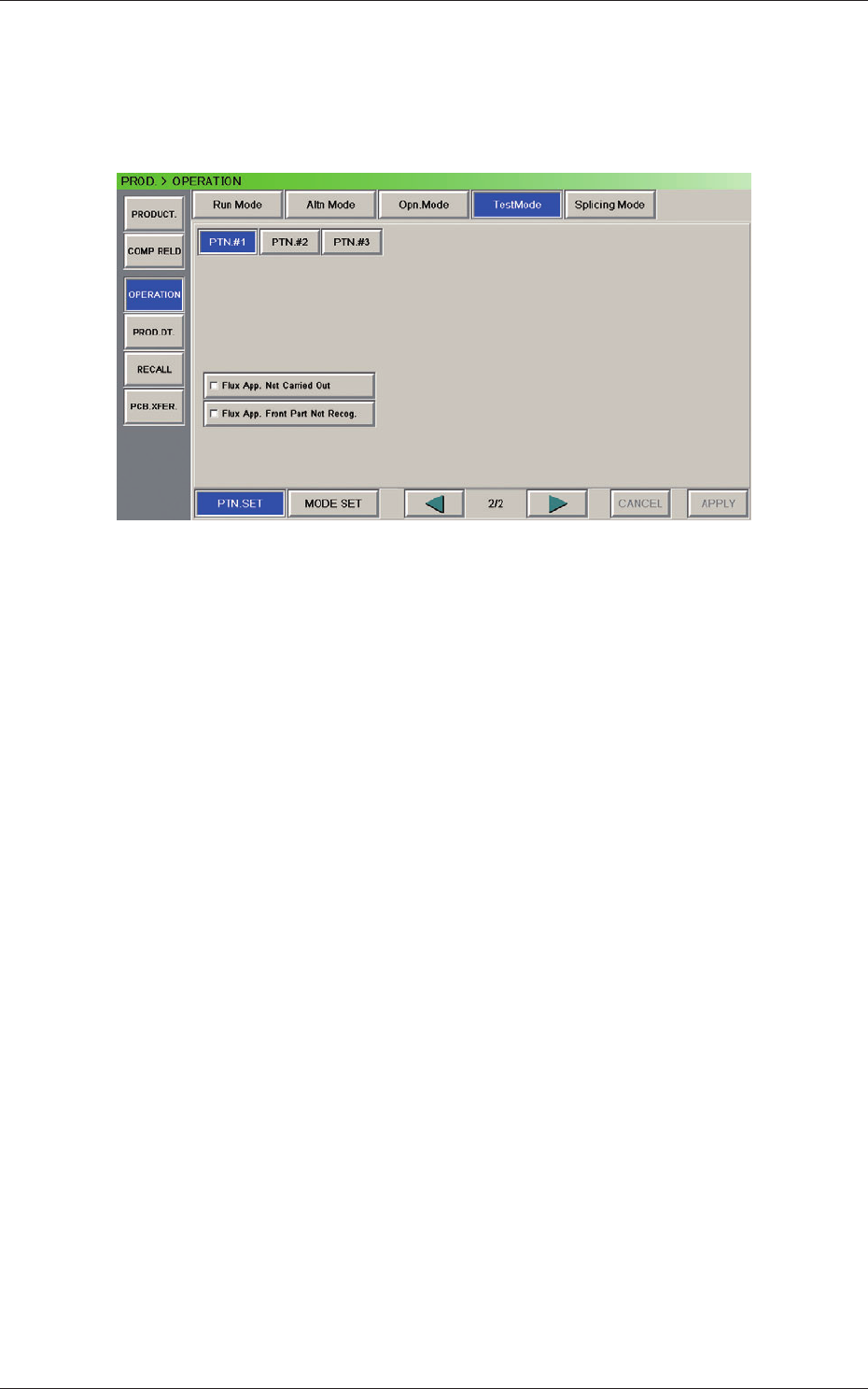
5.1.2 Selection of Test Mode
A test mode can be selected for the flux dispensing unit.
Open the "Test Mode" window (second page).
Fig. 15 "Test Mode" Window (Second Page)
Test Run Pattern
This section sets the test run contents.
The items related to the flux dispensing unit are as follows.
Flux App. Not Carried Out
Flux App. Front Part Not Recog.
5.1 "Operation" Menu
5-4
Tg1357-ID-SO
0703-003
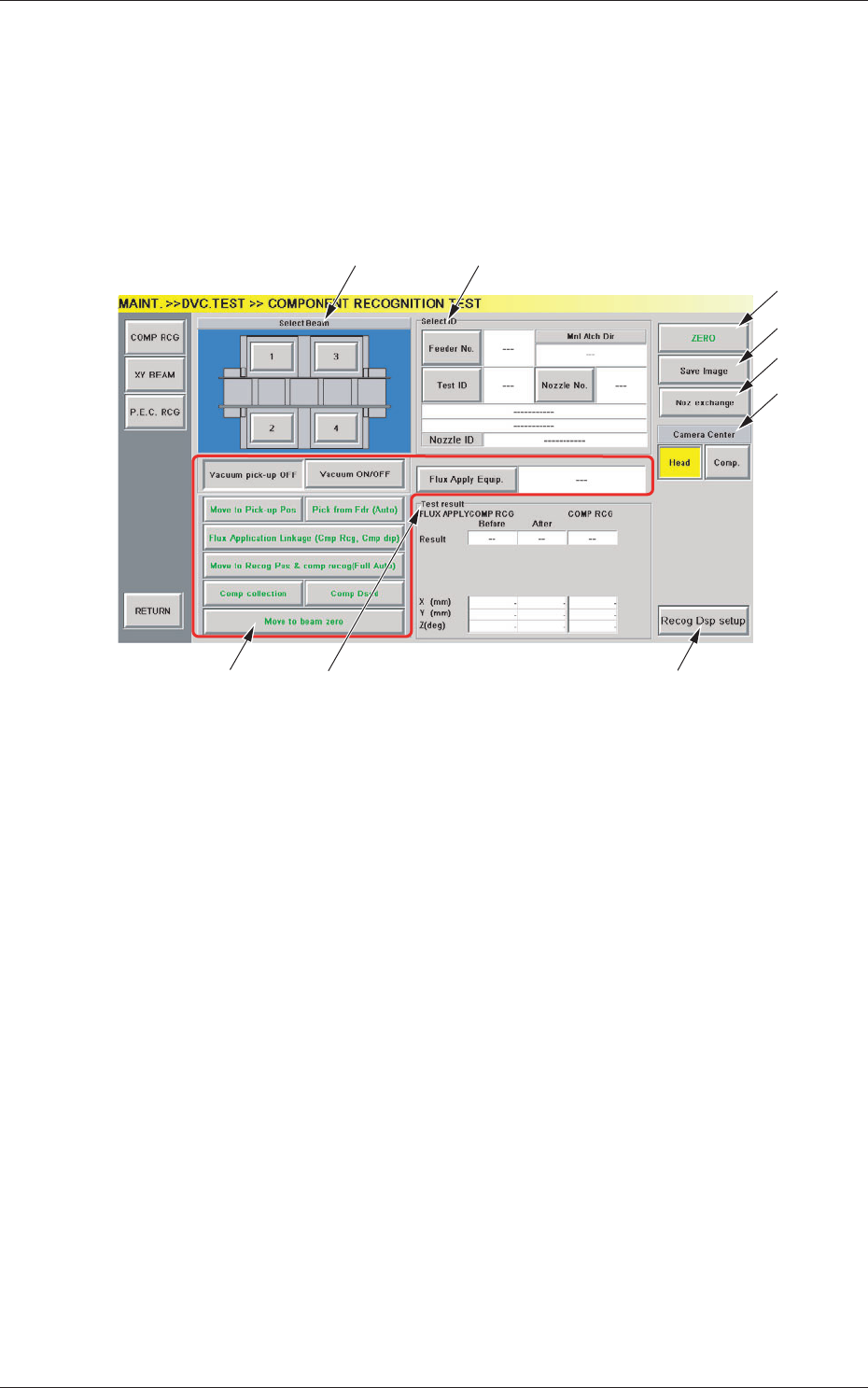
5.2 Component Recognition Test
This window enables you check whether or not the component designated
using a test ID can normally be recognized.
When the [COMP RCG] button on the "DVC. TEST" submenu bar is
pressed, the "COMPONENT RECOGNITION TEST" window opens.
[3]
[4]
[1] [2]
[9]
[5]
[6]
[7]
[8]
Fig.16 "COMPONENT RECOGNITION TEST" Window
[1] Beam Selection Buttons
Each X/Y beam in the graphic image of the machine is provided with a
button function.
Select the X/Y beam on which a component recognition test must be
performed.
[2] "Select ID" Group Box
The following buttons and text boxes are arranged and used to display
the specified values.
[Feeder No.] Button
When pressed, this button opens the "Feeder No." selection
window, enabling you to specify the feeder from which test
components should be picked up.
[Test ID] Button
When pressed, this button opens the "Test ID Selection
" window,
enabling you to specify the component ID for the recognition
test.
5.2 Component Recognition Test

5-5
Tg1357-ID-SO
0703-003
"Nozzle ID"
Displayed is the nozzle type specified with the [Test ID] button.
[Nozzle No.] Button
When this button is pressed, the "Select ID >> Nozzle No."
window opens, enabling you to set the nozzle No. to be used for
the recognition test.
Mnl Atch Dir
Displayed is the direction (reverse or same direction) of
component to be attached by hand.
Def Direct :
This indicates that a component will be attached
in the reverse direction in comparison with the
direction of the components supplied from each
feeder.
Same Direct :
This indicates that a component will be attached
in the same direction as that of the components
supplied from each feeder.
[3] Operation Buttons
[Vacuum ON/OFF] Button
This button can the used to trun on or off the vacuum for the
nozzle.
Either the [Vacuum pick-up OFF] or the [Vacuum pick-up ON]
button appears on the left side of the [Vacuum ON/OFF] button
according to the current vacuum condition.
[Move to Pick-up Pos] Button
This button can be used to manually attach a component.
When the [START] button on the operation panel is pressed in
ten seconds after this button is selected, the head on the X/Y
beam selected in [1] moves the center (zero) position and the
nozzle No. specified in [2] moves (rotates) toward the front side.
[
Pick from Fdr (Auto)] Button
This button can be used to automatically take out a component.
When the [START] button on the operation panel is pressed in
ten seconds after this button, the head on the X/Y beam selected
in [1] moves the feeder No. position specified in [2] and takes out
a component.
5.2 Component Recognition Test