OM-1352-003_w.pdf - 第55页
6-6 Tg1357-ID-SO 6.1.2 Setup for the Component Library "Control Data" for T op Components The mark coordinates are set to recognize the land for the bottom components. • Set the pattern program as follows: Set …

6-5
Tg1357-ID-SO
0703-003
Feeder Alternate
Select "Enable" or "Disable" to determine whether or not the feeder
alternate function should be used.
Disable :
The feeder alternate function is not used.
Enable :
The feeder alternate function is used.
Fdr No.
When "Enable" is selected for the feeder alternate function, set the
destination feeder No. (Fdr No.) of the feeder that will work in place of
the feeder where a component pickup error has occurred in succession.
Reference
Refer to "1.4 Placement Feeder Location Data" in "Chapter 3" of the
instruction manual (Vol. 3 for the main machine) for details.
Setting Procedure of Placement Feeder Location Data
Procedure
(1) Press the icon ( ) when the "Placement Feeder Location" tab sheet is
active. The "Feeder Base" subtab sheets become valid and can be used
to specify each flux dispensing unit.
(2) Select each unit No. button ([Unit #1] through [Unit #4] buttons) in the
required "Feeder Base #" subtab sheet.
(3) Specify parameters (number of rotations) in the "No. of Rot. [rot.]" text
boxes for the specified unit No.
6.1 Pattern Program
6-6
Tg1357-ID-SO
6.1.2 Setup for the Component Library "Control Data" for Top
Components
The mark coordinates are set to recognize the land for the bottom
components.
•
Set the pattern program as follows:
Set "Individual Recognition" to "Enable" and "V Data" to "11".
(X1 to X2 and FM2 are invalid data items).
11: Individual Recognition (2-point recognition) is performed.
Note
The "V Data" for using this machine should be set to "11".
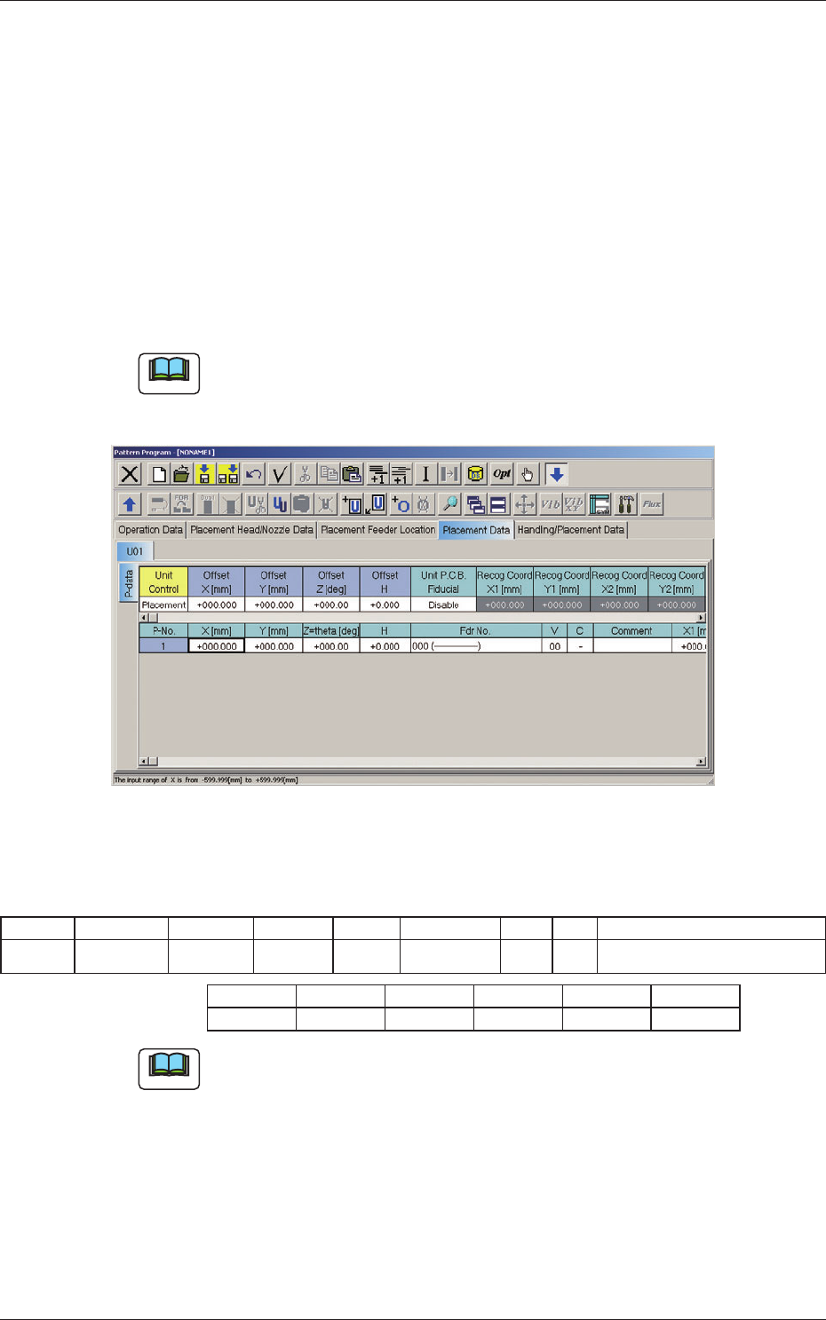
Fig.22 "Placement Data" Tab Sheet
Table
2
P-No X [mm] Y[mm] Z[°] H Fdr No. V C Comment
2 +020.000 +025.000 +045.00 +1.200 703(TOP) 11 - Placement of top component
X1 [mm] Y1 [mm] X2 [mm] Y2 [mm] FM1 FM2
+000.000 +000.000 +000.000 +000.000 02 02
Note
The focus range for the PEC recognition camera is limited, so when the V
Data is set to "11" and "H < -1.5 mm", or in the case of "+ 1.5 mm < H" (H
is not within the range of +/- 1.5 mm), an error message is received.
0703-003
6.1 Pattern Program
6-7
Tg1357-ID-SO
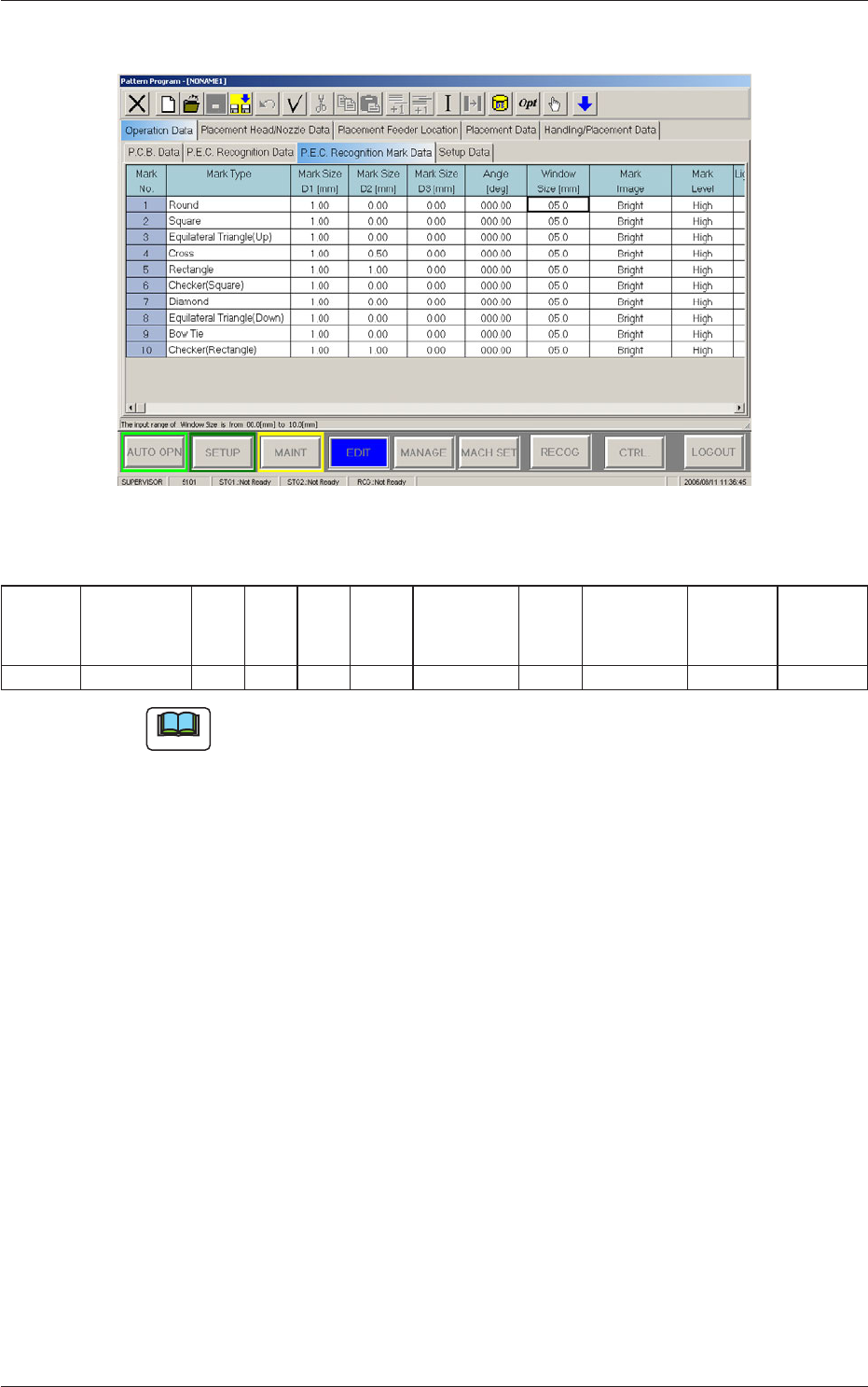
•
For PEC recognition mark data, set the Mark Type to
"Round".
Fig.23 "For PEC recognition mark data" Tab Sheet
Table
3
Mark No Mark Type D1
[mm]
D2
[mm]
D3
[mm]
Angel
[deg]
Window
Size [mm]
Mark
Image
Mark Level Lighting
Level
Coax
Lighting
Level
Ring
2 Round 0.20 0.00 0.00 000.00 05.0 Bright High Standard Standard
Note
(a) When "Round" is selected, the value for D1 is to be 0.13 mm or more.
(b) When "Round" is selected for normal PEC recognition (global,
divided, or individual), or when other than "Round" is selected while
"Individual Recognition" is set to "Enable" and "V Data" is set to
"11", an error message is received.
(c) When "Round" is selected, the "Window Size" data is invalid because
the inspection range is set automatically in the machine so that the
other lands on the bottom components are not recognized by mistakes.
0703-003
6.1 Pattern Program