OM-1352-003_w.pdf - 第57页
6-8 Tg1357-ID-SO 6.2 Component Library The component library data must be edited for the components that can be handled by the flux dispensing unit. When the "Control Data" tab is pressed in the "Component …
6-7
Tg1357-ID-SO
•
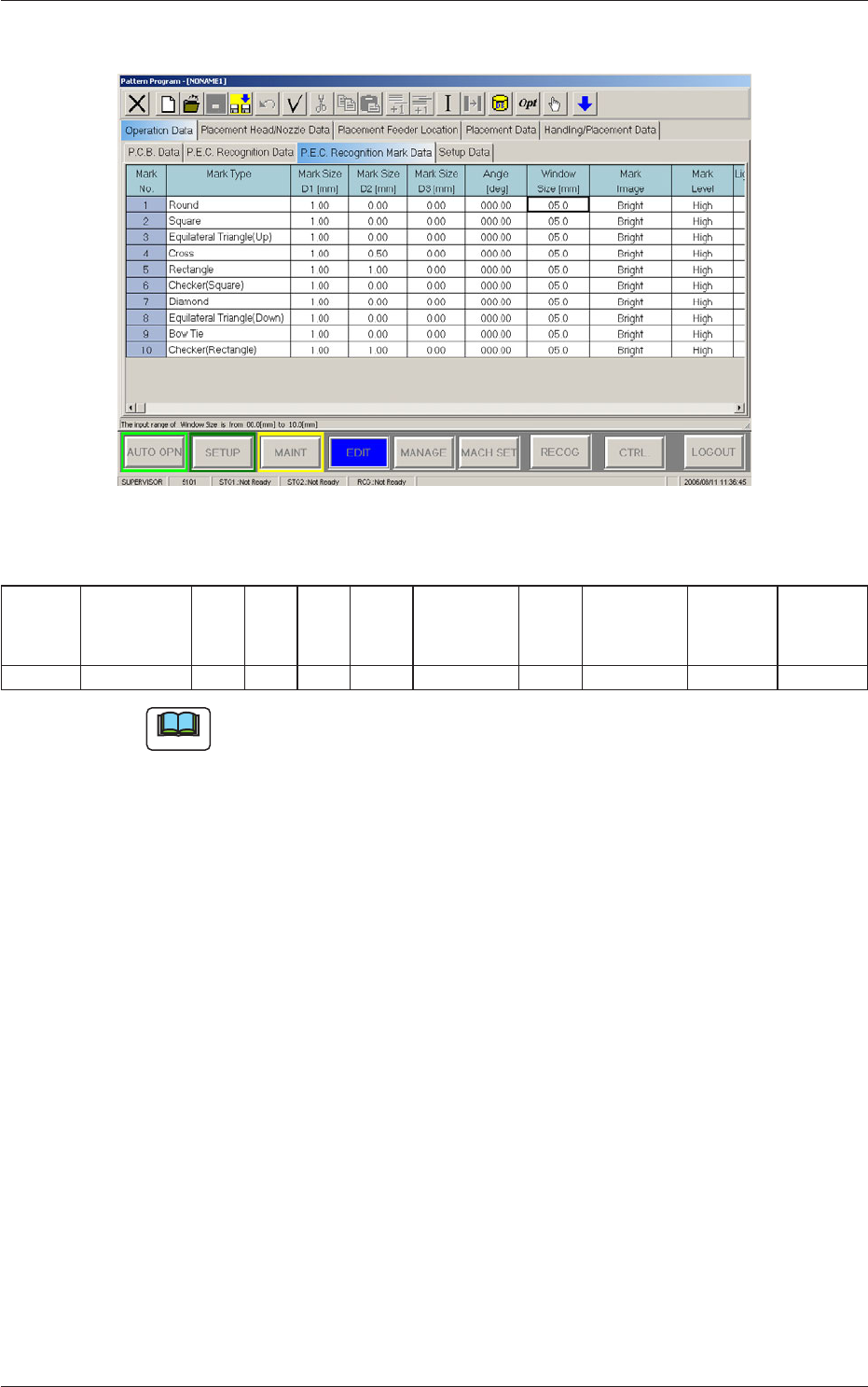
For PEC recognition mark data, set the Mark Type to
"Round".
Fig.23 "For PEC recognition mark data" Tab Sheet
Table
3
Mark No Mark Type D1
[mm]
D2
[mm]
D3
[mm]
Angel
[deg]
Window
Size [mm]
Mark
Image
Mark Level Lighting
Level
Coax
Lighting
Level
Ring
2 Round 0.20 0.00 0.00 000.00 05.0 Bright High Standard Standard
Note
(a) When "Round" is selected, the value for D1 is to be 0.13 mm or more.
(b) When "Round" is selected for normal PEC recognition (global,
divided, or individual), or when other than "Round" is selected while
"Individual Recognition" is set to "Enable" and "V Data" is set to
"11", an error message is received.
(c) When "Round" is selected, the "Window Size" data is invalid because
the inspection range is set automatically in the machine so that the
other lands on the bottom components are not recognized by mistakes.
0703-003
6.1 Pattern Program
6-8
Tg1357-ID-SO
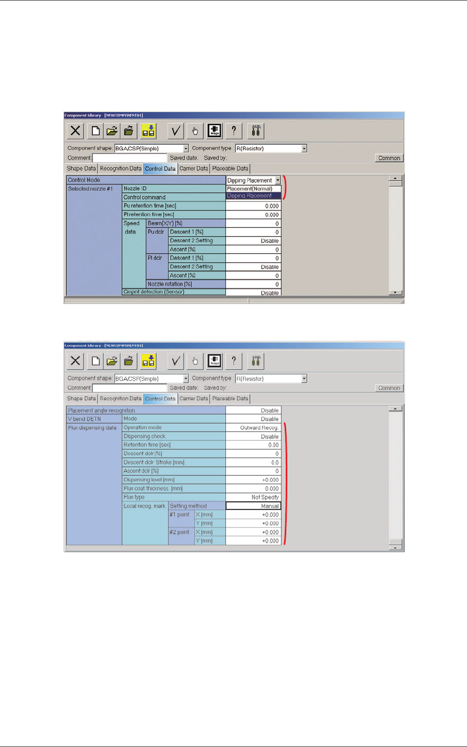
6.2 Component Library
The component library data must be edited for the components that can be
handled by the flux dispensing unit.
When the "Control Data" tab is pressed in the "Component Library" edit
window, the corresponding tab sheet appears inside the window.
Fig. 24
[2]
Fig. 25
[1] Control Mode
"Placement (Normal)" or "Dipping Placement" can be selected from the
"Control Mode" combo box.
Placement (Normal) :
When this option is selected, the machine
performs normal processing of component
placement.
Dipping Placement :
When this option is selected, the components
are dipped in flux.
0703-003
6.2 Component Library
[1]
6-9
Tg1357-ID-SO
[2] Flux dispensing data
Operation mode
Operation mode settings.
Outward Recog. : Ball + Outline → Flux application → Outline
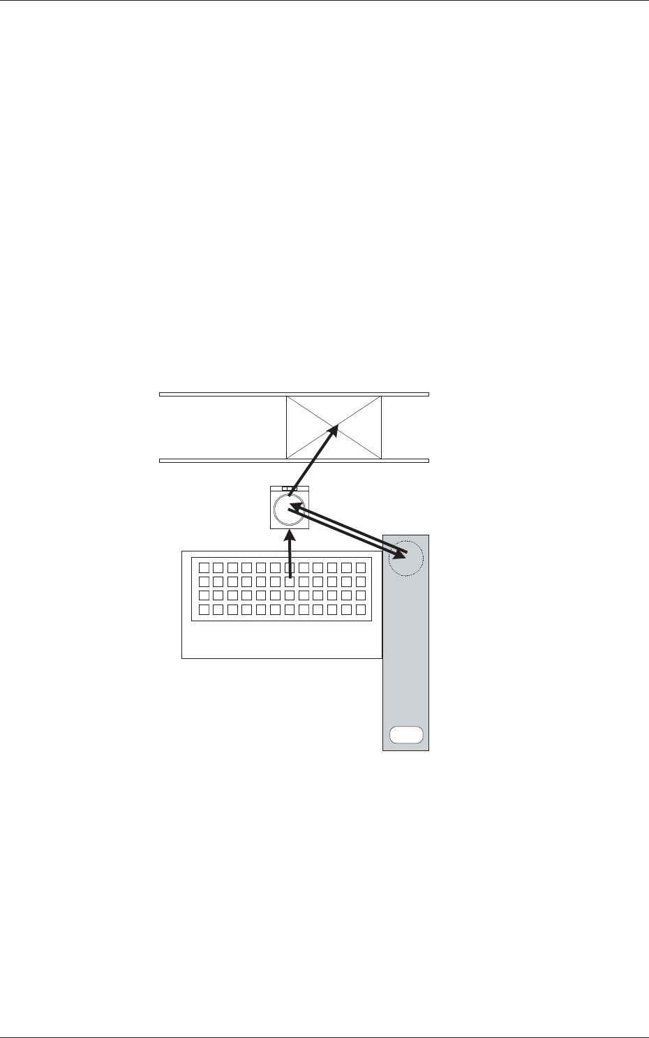
Bump Recog. : Ball → Flux application → Ball
•
Outward Recog. mode
In the case that the bump can not be recognized after the flux
application, then this mode is used.
Perform the bump recognition and outline recognition before the flux
application, and again perform the outline recognition after the flux
application.
Based on the position relationship resultant from the outline recognition
before and after the flux application, calculate the bump position and
perform placement.
5. Placement
2. Component Recognition
(Bump, Outline)
4. Component Recognition (Outline)
1. Component Pick up
Multi-Layer Tray Feeder
3. Flux Application
Flux Dispensing Unit
Fig.26
•
Bump Recognition mode
In the case that the bump can be recognized even after the flux
application, then this mode is used.
Perform the bump recognition in each of "2. Component Recognition
(Bump, Outline)" and "4. Component Recognition (Outline)" steps.
0703-003
6.2 Component Library